What Is Meshing: Unlocking the Power of 3D Geometry

Mesh generation is crucial in engineering simulations such as finite element analysis and computational fluid dynamics. It divides a complex object or scene into small, discrete cells or elements called a mesh. The meshes resemble tiny building blocks that fit together tightly, leaving no gaps. This allows computers to simulate the behavior of the object or scene in a thorough and precise manner.
The physical world can be explained through partial differential equations (PDEs), which outline how certain physical factors (like temperature, pressure, etc.) alter in relation to independent variables (namely, the three spatial coordinates - and time).
For simple situations and simply-shaped objects, it is possible - given the governing partial differential equations (derived by physicists and mathematicians in the last three centuries) and their conditions (e.g., initial temperature, the temperature on the walls) - to find an analytical solution, i.e. a mathematical "input-output machine" providing the relationship between the independent and dependent variable.
Why should we be concerned with meshing?
Meshing is crucial in helping engineers solve partial differential equations over complex objects using numerical methods. Although it can be challenging, it is necessary. Do not overlook its importance.
In fact, finding analytical solutions to complex shapes is practically impossible!
Numerical methods help to understand how objects and systems behave under different conditions, i.e. to simulate an object in 3D from an engineering point of view (Computer-Aided Engineering or CAE).
Many people like the concept of meshing, but most engineers would like to go straight to the postprocessing phase (i.e. looking at CAE results and finding inspiration for new designs) rather than spending time with building a mesh.
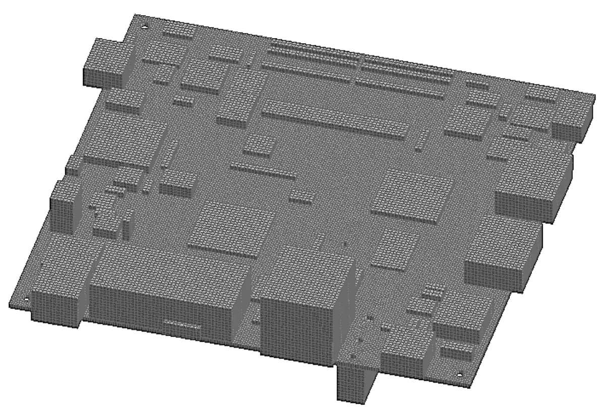
In the article, we will review the various meshing technologies and the new AI approaches to simulation that will alleviate design engineers from the cumbersome task of meshing.
What Is Meshing? Why Meshing?
Meshing is a fundamental process in engineering that involves discretizing a spatial domain into a set of discrete elements or cells. Meshing is widely used in various fields, such as computer-aided engineering (CAD), computer-aided engineering for automotive and other industries (Finite Element Analysis or FEA and Computational Fluid Dynamics or CFD), computer graphics, and computer vision.
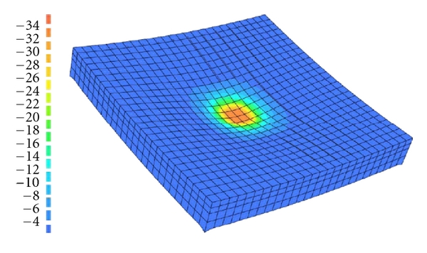
Meshing is crucial in simulations, analyses, and visualizations of complex systems and structures.
Meshing enables engineers and researchers to accurately represent objects or scenes' complex geometry and physics, allowing for numerical computations and simulations to have an input (together with information on physics, initial conditions, and boundary conditions) to work on. The quality and accuracy of the mesh directly impact the reliability and validity of the results obtained from engineering simulations. Therefore, meshing is critical in the engineering workflow, ensuring accurate and reliable analyses and predictions.

Types of Meshing Techniques
Meshing, or dividing a complex object or scene into smaller elements or cells, is fundamental in engineering simulations. Meshes allow computers to accurately simulate the behavior of objects or systems under different conditions, aiding engineers in making informed decisions. There are two main types of mesh: structured mesh and unstructured mesh.
Structured Meshing
Structured meshes are grids that follow a regular pattern, with equally spaced elements in a systematic arrangement. Think of it like a checkerboard or a Sudoku puzzle, where each cell has the same size and shape.
Structured meshes were among the earliest meshing methods developed. They were widely used in the early days of computational simulations due to their simplicity and ease of implementation since the earliest meshed object had quite simple (not to say naive) geometrical shapes! They were especially popular in fields of physical phenomena like structural mechanics and heat transfer.
Unstructured Meshing
On the other hand, unstructured meshes do not follow a regular pattern and have elements of varying shapes and sizes. They are more like a puzzle with irregular pieces that can fit together in any configuration. The companion figure illustrates this point, showing regular "cubes" that can fit wind tunnel walls but could in no way fit the complex geometry of a Le Mans Racing car.
Those meshes are highly flexible and adaptable, making them suitable for complex geometries and irregular shapes. They allow for finer mesh resolution in areas of interest and coarser resolution in less critical areas, resulting in more accurate and efficient simulations.
The development of non-structured meshes was a significant advancement in meshing technology. It allowed engineers to simulate complex geometries more accurately, such as in aerodynamics simulations.
Unstructured meshes also facilitated higher-order numerical methods, which provide more accurate results with fewer elements, saving computational resources and time.
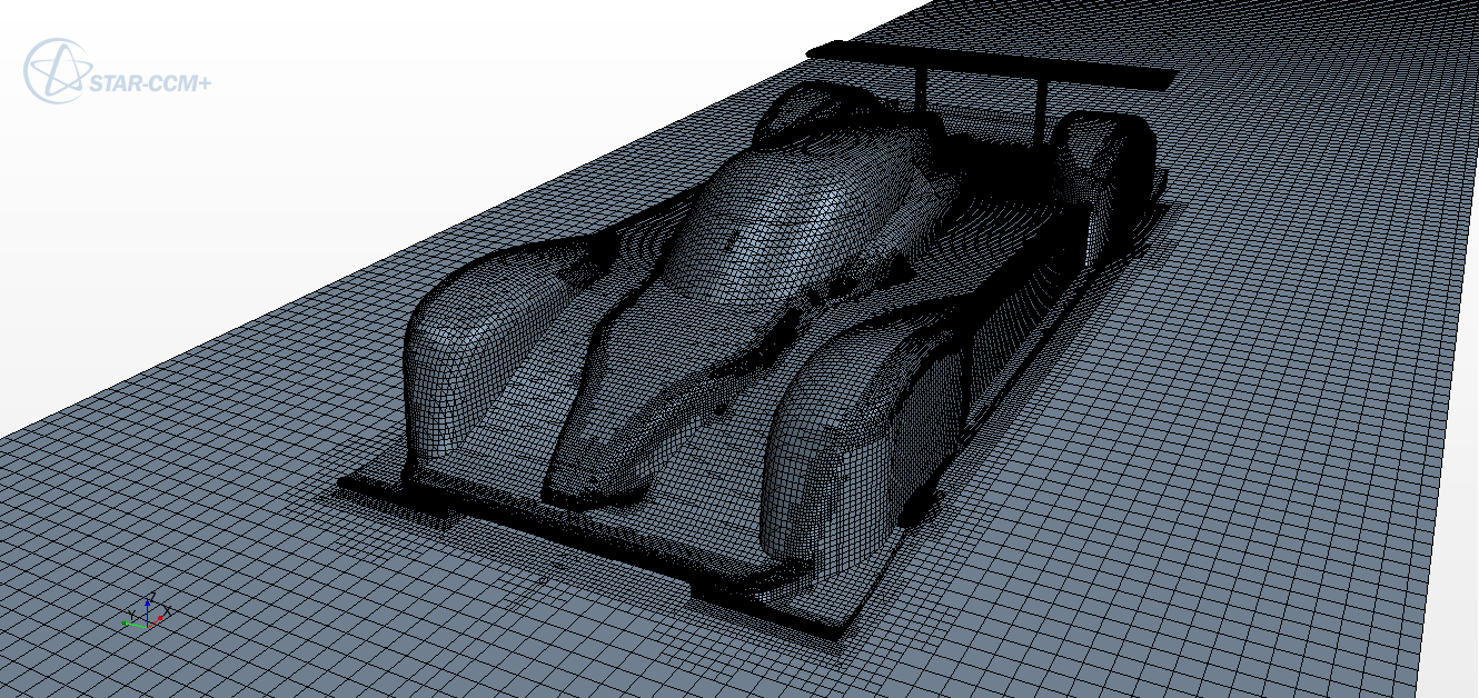
Structured or Not?
Today, both structured mesh and unstructured meshes have their applications and limitations. Structured meshes are still used in certain scenarios where the geometry is simple and regular, and the focus is on computational efficiency.
On the other hand, unstructured meshes are preferred in complex simulations that require high accuracy and flexibility in handling irregular geometries.
3D Models and Finite Element Analysis (FEA)
Various approaches to mesh generation are available for the Finite Element Method (FEM or FEA). These include structured, unstructured, and adaptive techniques.
Structured meshes, composed of regularly shaped finite elements, such as quadrilaterals or hexahedra, are well-suited for simple geometries and can efficiently represent smooth variations in the Finite Element Method solution. They facilitate easy data storage and interpolation.
Unstructured meshes are more flexible than structured grids and can handle complex geometries, like in CFD. Triangular or tetrahedral elements are commonly used, allowing irregular shapes and boundary-conforming meshes. Delaunay triangulation and advancing front methods are often employed for generating unstructured meshes for the Finite Element Method.
Adaptive Meshing
Adaptive meshing techniques in Finite Element Analysis (FEA) or CFD dynamically refine or coarsen the mesh based on solution characteristics. This enables efficient resolution of localized features or areas of interest while reducing computational costs elsewhere. Adaptive meshing methods typically involve error estimators, h-refinement (refining elements), or p-refinement (increasing polynomial order in FEA). This huge mesh refinement topic would deserve an article on its own!
From 3D CAD Geometry to Mesh
Converting a 3D CAD model, i.e. a description of a continuous geometric space, into a suitable mesh for CFD simulations requires careful CAD cleaning and surface mesh generation.
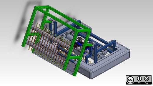
CAD "cleaning" involves preparing the model by removing unnecessary details and ensuring a watertight surface representation. Techniques like Surface Wrapping can create closed and continuous surface meshes from CAD.
CAD cleaning and surface mesh generation are vital steps in the CFD workflow, ensuring the accuracy and reliability of simulations. By carefully addressing these steps, engineers can obtain realistic and effective results for analyzing fluid flow phenomena.
Apart from representing a potential bottleneck not allowing the entire mesh volume generation to proceed, there are several issues arising from CAD cleaning is not properly addressed
Mesh Quality Issues
Insufficient CAD cleaning can result in poor mesh quality. Unresolved small features or gaps in the CAD model can lead to distorted or poorly shaped elements in the mesh. Such elements can cause numerical instabilities, convergence difficulties, and inaccurate flow physics representation.
Boundary Condition Errors
Inaccurate CAD cleaning can affect the definition of boundary conditions. Unresolved or incorrectly represented boundaries can result in improper boundary conditions, leading to unrealistic flow behavior or incorrect forces acting on the system.
Simulation Instabilities
Inadequate CAD cleaning can introduce irregularities in the mesh, causing abrupt changes in element sizes or poor connectivity between a dense and less dense mesh. These irregularities can lead to simulation instabilities, such as numerical oscillations or divergent solutions, compromising the reliability and usefulness of the simulation. It is not reasonable to think that "the finer the mesh, the better the solution," both in terms of computational overheads and in terms of losing focus on the mesh quality.
Meshing Techniques - Best Practices: CFD
The quality of a mesh greatly affects the accuracy and convergence of CFD simulations.
A high-quality mesh should have the following characteristics (this is not an exhaustive list):
Sufficient resolution
The mesh should be fine enough to accurately capture the flow features of interest, such as boundary layers, shock waves, and vortices. Refining the mesh in regions where the flow variables change rapidly is important.
Orthogonality
In structured meshes, the angles between the adjacent cell faces should be close to 90 degrees to avoid numerical errors. In unstructured meshes, the angles between the cell faces should be as close to equiangular as possible.
Aspect ratio
Aspect ratio (AR) refers to the ratio of the longest side of a cell to the shortest side. High aspect ratios can result in inaccurate simulations and poor convergence. Keeping the AR of mesh cells within reasonable limits is important, typically below 10.
Other details, such as skewness, are important for the quality of the mesh and solver results.
Grid Independence Study
Grid independence study is crucial in CFD simulations to ensure the mesh resolution does not affect the results. It involves performing simulations with different mesh types and resolutions and comparing the results. The simulation is considered grid-independent if the results show good agreement and do not change significantly with increasing mesh resolution. A grid independence study can help to establish the appropriate mesh resolution for accurate simulations.
Boundary Layer Meshing
The boundary layer or BL (see figure) is the region of fluid flow near a solid object's surface where the fluid's velocity changes rapidly.
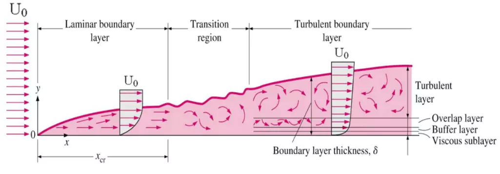
The accurate BL meshing is crucial for accurately capturing the flow physics. Here are some best practices for BL meshing:
Y+ value
The Y+ value is a dimensionless parameter used to determine the size of the first cell adjacent to the wall. It represents the distance of the first cell from the wall in terms of the local wall distance and the friction velocity of the flow.
For accurate BL resolution, it is recommended to keep the Y+ value between 1 and 5. This ensures the first cell is small enough to capture the viscous effects near the wall.
Prism layers, or inflation layers
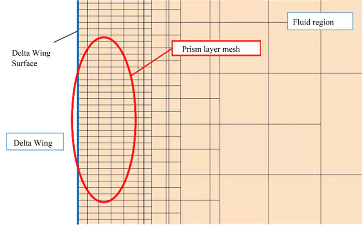
Prism layers resolve the BL in unstructured meshes. They are typically added on top of the surface of the solid object to capture the velocity gradients near the wall accurately.
It is important to ensure that the prism layers have sufficient resolution and extend beyond the region of interest to avoid the influence of the solid object on the flow.
Mesh Sensitivity Analysis
Mesh sensitivity analysis involves testing the sensitivity of the simulation results to changes in the mesh. It helps identify regions where the mesh may need refinement to improve the accuracy of the simulations.
It is recommended to perform mesh sensitivity analysis by systematically varying the mesh resolution in different regions of interest and comparing the results to establish the optimal mesh for accurate simulations.
Grid Generation Software
The choice of grid generation software can significantly impact the quality of the mesh. Various commercial and open-source software is available for mesh generation, and it is important to choose software suitable for the simulation's specific geometry and flow conditions.
The capabilities and limitations of the chosen grid generation software should be understood to follow the best practices recommended by the software developers.

Mesh Repair and Cleanup
After generating the mesh, it is important to perform mesh repair and cleanup operations to ensure it is free from errors and inconsistencies. Mesh repair operations may include fixing poor-quality mesh elements, such as distorted, inverted, or cells with negative volumes. Mesh cleanup operations may involve removing unnecessary cells or refining the mesh in critical regions.
It is crucial to thoroughly check the mesh for errors and inconsistencies and perform necessary repairs and cleanup operations to ensure a high-quality mesh.
Meshing for Deep Learning
Let us introduce a different type of meshing, apparently not related to CAE meshing.
In Deep Learning and image recognition in 3D, meshing plays a crucial role in representing the 3D geometry of objects or scenes.
Unlike traditional image recognition in 2D, where images are represented as 2D grids of pixels, DL in 3D requires the representation of 3D geometry as a discrete geometric mesh structure. This mesh structure can be used as input data for DL models to perform tasks such as object recognition, scene understanding, or 3D reconstruction.
The requirements for meshing in DL or image recognition in 3D may differ from those in CAE simulations.
In DL, the mesh structure may need to capture fine details of the 3D geometry, such as surface features, edges, and corners, which are important for object recognition or scene understanding. Additionally, the mesh may need to be adaptive, allowing for local mesh refinement or coarsening based on the specific task or input data.
Various techniques have been proposed for meshing in DL or image recognition in 3D, including voxel-based, point cloud-based, and mesh-based methods. Depending on the specific task and application, these methods have strengths and limitations.
Voxels and Deep Learning
Voxel-Based Methods Voxels, short for volumetric pixels, are 3D counterparts of pixels in 2D images, representing discrete volumetric elements in a 3D space. Voxel-based methods involve dividing the 3D space into a regular or irregular grid of voxels and using the values or attributes associated with each voxel to represent the 3D geometry.
One of the main advantages of voxel-based methods is their simplicity and efficiency in representing 3D geometry.
Also, voxels can be processed using 3D convolutional neural networks (CNNs), i.e. deep learning models specifically designed to process volumetric data.
However, voxel-based methods also have limitations. Voxels' discrete nature mesh size can result in high memory and computational requirements, especially for large 3D data. Voxel-based methods may also suffer from limited resolution, as the increased resolution may increase memory and computational requirements.
Point Cloud-Based Methods and Deep Learning
Point clouds are sets of 3D points that represent the surface or geometry of an object or scene. Point cloud-based methods directly process and analyze the 3D points without explicit meshing. Point clouds can be acquired from various sources, such as 3D scanners, LiDAR sensors, or generated from 3D models.
One of the main advantages of point cloud-based methods is their ability to capture fine details of the 3D geometry, as points can accurately represent complex shapes or structures. Point cloud-based methods also have relatively low memory and computational requirements compared to voxel-based methods, as only the coordinates and attributes of the points need to be processed. Point cloud-based methods are suitable for tasks that require precise geometric information, such as point cloud classification, object segmentation, or shape completion.
However, point cloud-based methods also have limitations: they may struggle with object shape mesh density, size, and orientation variations, as the point density or distribution may vary across different objects or scenes.
Mesh-Based Methods and Deep Learning
Meshes can accurately capture the surface features, edges, and corners of objects or scenes, making them suitable for tasks that require high geometric fidelity.
Mesh-based methods also have relatively low memory and computational requirements compared to voxel-based methods, as only the mesh's vertices, edges, and faces need to be processed.
Meshing is an important aspect of DL or image recognition in 3D. It plays a crucial role in representing the 3D geometry of objects or scenes, which is essential for accurate and efficient DL model training and inference.
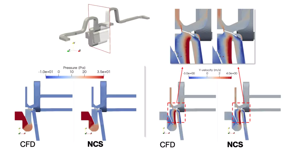
Is CAE Prediction Without Meshing Possible?
New AI techniques introduced in 2018, based on coupling image recognition with deep learning from CAD and CAE data, allow engineers to predict CAE-quality results without meshing toils!
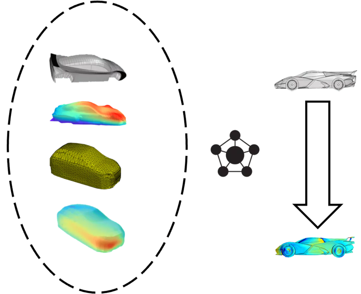
Thus, Deep Learning provides a "surrogate" of an accurate simulation without requiring CFD meshing or any meshing algorithms. The simulation process based on physics is replaced by a prediction process based on data-driven models. The advantage, apart from the response time of deep learning models, is that users do not need to worry about element quality and other specialist issues.
Conclusions
For engineers, the mesh represents a due task, although cumbersome. An efficient mesh, such as a hex mesh in CFD volume mesh generation, should be considered regarding mesh generation time and quality of CFD results.
We have reviewed the different types of meshes and the important topic of mesh quality.
We have seen a new way to associate a given geometry shape with a CAE result without a meshing process. The entire object to be simulated is captured with an AI approach inspired by Computer Vision.
The Deep Learning approach is promising. It will provide an exciting way to generate fast engineering predictions by exploiting datasets from numerical analysis data and making them available to product design engineers who need accurate simulation results but have no time to complete a high-end CAE simulation.


