What Is Machine Design Engineering? Types & Methods
Machine design engineering incorporates mathematics, materials science knowledge, and engineering expertise to create objects, mechanisms, machines, and tools.
This article will go through the machine design process with practical examples and real-world applications, mainly from mechanical design.
As we delve deeper into the topic, you will discover how engineers use machine design to turn innovative ideas into tangible products.
We will briefly expose some methods of this ever-evolving field and also touch upon modern machine learning software for engineering.
The Essence of Machine Design Engineering
Can you imagine a world without modern machinery and technology? Cars, airplanes, smartphones, and even our everyday kitchen blenders are all products of machine design engineering. Machine design encompasses mechanical ingenuity and creativity and is the heart of technological progress.
Let us start by considering the design of a classic internal combustion automobile engine and the concept of assembly of dynamic parts, moving on to the second example of conveyor systems.
Practical Examples in Mechanical Engineering - Different Machine Elements Assembled
A classic internal combustion engine is not just a haphazard assembly of parts. All the "machine elements" are designed to work together, from the cylinders and pistons to the crankshaft and timing belt.
With AI in mechanical engineering methodologies, designers calculate and configure these elements to create an engine that optimizes fuel efficiency, power output, and reliability.
Here, you see two basic tenets of machine design: a static (assembly) part and a dynamic part where components like crankshaft, piston, or valve are in motion transmitting forces.
The Fusion of Machine Elements in Machine Design
At its core, machine design engineering is about amalgamating diverse machine elements, as seen in the above example. Mechanical components like gears and bearings, electrical components such as wires, and hydraulic components like pipes join forces to produce and perform specific tasks. This interplay between different elements is what brings machinery to life.
Practical Example of Machine Design Process: Conveyor System
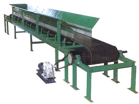
Picture a factory floor where products move from one station to another. This smooth operation is made possible by conveyor systems. Machine design engineers integrate mechanical elements like rollers and belts, electrical sensors for control, and hydraulic components for power transmission. The result is a synchronized flow of materials, where items are transported efficiently and precisely like in an orchestration.
Machine Design as a Cluster of Disciplines
As we see from the two above examples, machine design engineering is not a monolithic entity but a vast field with numerous sub-disciplines.
These specialized fields relate to various aspects of design, analysis, manufacturing, and operation of machines and tools.
The machine design engineering sub-disciplines include, for instance:
- Mechanical Engineering,
- Manufacturing Engineering,
- CNC Programming,
- CAD/CAM (Computer-Aided Design/Computer-Aided Manufacturing), and
- CMM (Coordinate Measuring Machines).
Mechanical Engineering
As the word says, mechanical engineering is concerned with mechanical systems design. The considerations a mechanical design engineer should bear in mind, i.e., the building blocks are
- engineering principles and methods in creating objects or adapting existing designs with adaptive design
- manufacturing methods
- thorough knowledge of prototype testing and or 3D simulation techniques to check the functional requirements of products
- materials engineering
CNC Machining
In CNC (Computer Numerical Control) machining, Machine Design Engineers craft precision parts using automated machine tools. The interplay between CAD software and CNC machines results in products manufactured that adhere to strict tolerances. This technology is at the foundation of various industries, from aerospace to medical devices.
Computer-Aided Manufacturing (CAD/CAM): Precision in Industrial Processes
In Machine Design, Computer-Aided Manufacturing (CAD/CAM) is central to reshaping how products are conceived, designed, and produced. Precision and efficiency are paramount in manufacturing, and CAD/CAM systems are essential to achieve these objectives.
The Functionality of CAD/CAM in Machine Design
CAD/CAM serves as the bridge between design (CAD) and production (CAM), streamlining the entire manufacturing process.
- During the design phase (CAD), engineers employ specialized software to generate 3D models of components or products. These digital models serve as virtual blueprints, specifying every dimension and detail with precision.
- In Computer-Aided Manufacturing (CAM), digital designs are translated into instructions that automated machines can execute. These instructions ensure manufacturing processes are carried out with high precision and consistency.
Practical Example: Aircraft Wing Rib Design
Consider the design of an aircraft wing. Machine Design Engineers use CAD software to create a 3D model of the wing, precisely specifying its geometry, engineering materials, and structural components. This digital representation is a platform for optimization, enabling engineers to fine-tune the design for optimal structural performance with FEA.
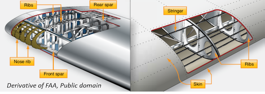
After finalizing the design, the transition from the digital to the physical realm occurs, where CAM takes charge.
Practical Machine Design Example: CNC Machining
CNC machining involves several crucial steps. It all starts with the Computer-Aided Design (CAD) phase, where engineers create a 3D model of the aerospace component, including its geometry, tolerances, and material specifications. Once the CAD model is complete, it's translated into G-code, a language the CNC machine understands. This code provides the machine design engineer with a precise recipe that guides the machine on cutting, moving, and operating its tools to recreate the digital design with exactitude.
Before the machining process begins, meticulous setup and calibration are necessary. The CNC machine's worktable is positioned carefully, and the cutting tools are secured precisely. The machine's accuracy depends on detailed calibration, ensuring every movement adheres to the specified design. The selection of materials and their secure fixturing are critical considerations.
The aerospace component's material is loaded onto the machine's worktable, firmly held in place by fixtures or clamps. Material selection and fixturing are vital to prevent any deviations from the design due to material inconsistencies or workpiece shifts.
Once the CAD design, G-code, and setup are in place, the CNC machine starts its tasks. The cutting tools are guided precisely across the workpiece, layer by layer, executing the tool paths with exceptional accuracy, adhering to the specifications outlined in the digital model.
Throughout the machining process, feedback systems are in place to monitor and make real-time adjustments as necessary. Probes and sensors can verify the accuracy of the workpiece, ensuring that the finished component conforms precisely to the above design specifications.
Finally, the aerospace component undergoes stringent quality control processes, including measurements, inspections, and tests, to ensure it meets all specified tolerances and requirements.
The result is a finished product that mirrors the original CAD design with unparalleled precision, ensuring that it fits seamlessly into the larger assembly, meeting the exacting standards of the aerospace industry.
Coordinate Measuring Machines
A Coordinate Measuring Machine (CMM) is a device that accurately measures the geometry of physical objects by sensing discrete points on the object's surface with a probe. CMMs use various sensors such as mechanical, optical, or laser.
An operator or computer precisely controls the probe's position to ensure accurate measurements. CMMs specify a probe's displacement from a reference position in a three-dimensional Cartesian coordinate system with XYZ axes. In addition to the rigid 3-axes motions, CCMs allow control of probe angle. This will enable CCMs to measure otherwise unreachable surfaces.
CCMs and Reverse Engineering in Machine Design
CCMs are also applied to facilitate a "reverse engineering design process." The CCM probes a prototype of a manufacturing sample. The CCM output in STL is imported into a CAD software system.
The CAD engineer exports the digital shape to computer-aided engineering for fluidic, thermal, electromagnetic, or structural testing.
Engineering Principles in Mechanical Design
Creating a functional and efficient solution requires a precise and structured design process in mechanical design. Engineers follow several steps: problem identification, conceptual design, detailed design, analysis and simulation, prototype development, testing and validation, and design optimization.
Each step is guided by technical considerations and assessments that ensure the final design is reliable and efficient.
Product Requirements
Designing a product starts with identifying the problem and specifying the requirements for the solution. This requires a technical examination of the issue and considering factors such as load-bearing capacity, dimensional constraints, operating conditions, and environmental factors.
Concept Design
Next, engineers generate various possible solutions during the conceptual design phase. These concepts are sketches, mathematical models, simulations, and feasibility studies. Technical assessments are performed to determine the viability of each concept against the specified criteria.
A novel approach is to democratize simulation tools with machine learning (more precisely, deep learning), allowing anyone in the design process to query an AI app - for instance, to find an optimal heat exchanger design (see figure). AI can be broadly classified as aiming at prediction by labeling/classifying data or making numerical continuous predictions. In the field of numerical prediction, AI can provide surrogates for more cumbersome solutions, helping mechanical engineers to design better existing machines or new machines.
But let us continue to describe the traditional design process that most engineering design departments still follow.
Once a promising concept is identified, the design process advances to the detailed design phase. Engineers calculate and specify every component, from the smallest bolt to the most critical load-bearing element. Materials, dimensions, tolerances, and manufacturing processes are defined with exactitude.
Technical rigor characterizes the fourth stage of the design process. The workflow holds for mechanical design but is valid in general for any process of designing machines and other equipment.
Virtual Iterations
The performance of components or their assemblies is subjected to rigorous analysis and simulation with High-Fidelity CAE (Computer-Aided Engineering software).
- Finite Element Analysis (FEA) assesses solid mechanics properties, such as stress distribution and structural integrity;
- Computational Fluid Dynamics (CFD) is utilized for fluid flow analysis, encompassing internal and external flows as well as heat transfer.
- The role of AI is to provide surrogates of the above main types of simulation to allow designers access to engineering prediction within a friendly environment and with the knowledge of design specifications but without skills in simulation, get a solid mechanics, fluid or electromagnetic prediction of a designed machine and share it with other designers, management or final customers.
Physical Iterations - Prototype Testing
Prototype development is the translation of theoretical and virtual considerations into physical reality. This stage requires precise technical execution, including precision machining, welding, or advanced manufacturing techniques. Prototypes are tested, and the technical data from these tests informs any necessary refinement in mechanical design (or other types of design). This is called a "physical" iteration.
Since there are material, energy, and logistic costs related to physical design iterations, there is a growing trend to optimize the number of virtual Vs physical iterations. Also, while on one hand, it is possible to accelerate virtual iterations via massive hardware investments or application of AI (thus reducing time-to-market) on the other hand there are physical limits to the construction, transportation, and laboratory set-up times within the physical iteration.

Technical validation is the penultimate stage. Components and mechanical systems undergo various specialized tests, encompassing mechanical stress tests, thermal testing, and environmental trials.
Technical data collected during this stage serve as empirical evidence of the design's performance under real-world conditions.
Design Optimization: Closing the Loop
In the final stage of the design process (and in the closure of this article), engineers assess the data from testing and validation to identify opportunities for design optimization. Technical refinements may include alterations in material selection, component geometry, or manufacturing processes.
The achieved goal is to enhance technical performance, efficiency, and reliability.
Once again, virtual approaches via classic CAE or AI offer the tremendous advantage of the coupling of algorithms from optimization and simulation, thus making the optimization loop more affordable and less rigid than in the past.
Welcome to the era of real-time optimization with AI!


