What Is Battery Cooling and How Does It Work?
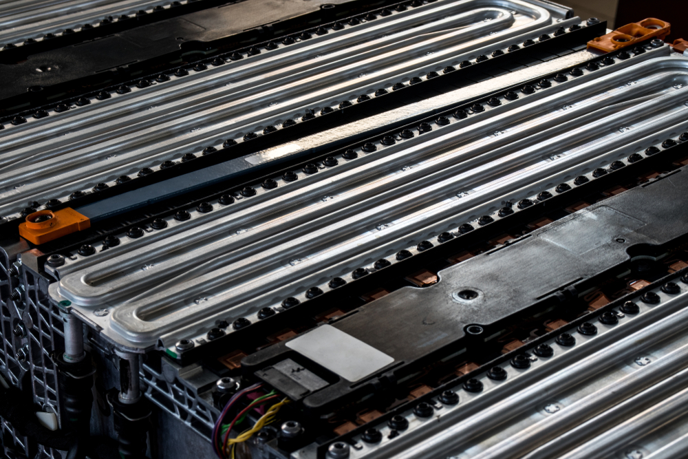
Battery cooling is the process of controlling the temperature of an electric vehicle (EV) battery to keep it within safe and efficient operating limits. Effective cooling prevents overheating, maintains performance, and prolongs battery life.
Battery thermal management systems (BTMSs) impact vehicle safety and performance. Electric vehicle (EV) owners want to be reassured about the reliability and autonomy of their cars. Concentrating engineering efforts on the EV battery cooling system and its optimization can guarantee electric vehicle durability and safety while allowing for fast charging.
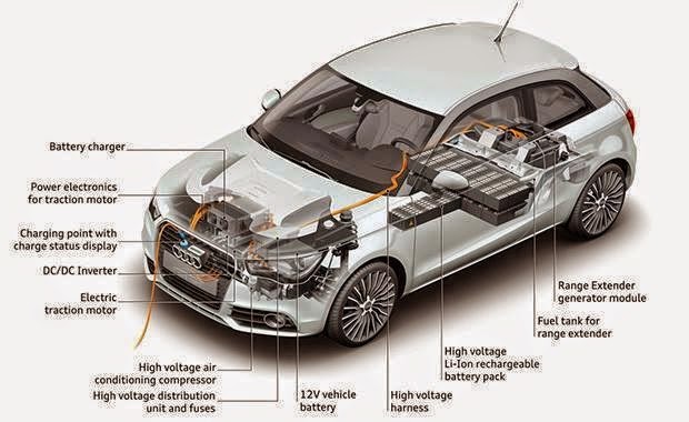
- EVs are characterized by battery packs that store energy in chemical form. These battery packs comprise several cells connected in series and parallel to achieve the desired voltage and capacity.
- Lithium-ion (Li-ion) batteries are the most common type used in EVs thanks to their high energy density, long cycle life, and relatively low self-discharge rate.
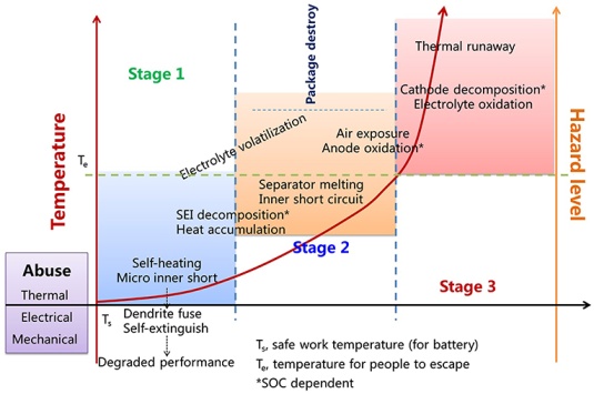
- Li-ion batteries generate heat during charging and discharging and must be kept within an optimal range of temperature. In the “thermal runaway” phenomenon, if a battery becomes too hot, it can lead to a dangerous condition where it rapidly releases energy, potentially causing fires or explosions.
- Cooling helps maintain battery modules at optimal operating temperatures, improving battery efficiency and extending lifespan. An efficient thermal management system also ensures consistent performance under varying conditions (e.g., extreme temperatures and the sought-after fast charging).
So, in the face of those dangers, let’s remain calm - the situation is under control!
In the following, we will focus on cooling systems for electric vehicle batteries and the battery thermal management system, particularly discussing direct and indirect cooling, starting with a brief introduction to heat exchange:
We will discuss:
- Elementary Overview: Liquid Cooling System Vs Air Cooling System
- Air Cooling: Forced Vs. Natural Convection (Passive Cooling Vs Active Cooling)
- What is Thermal Equilibrium?
- What is the Difference between Natural and Forced Convection?
- Liquid Cooling: Air Cooling Vs. Liquid Cooling Methods
- Heat Transfer Coefficient for Air and Liquids
- Why Are Liquid Cooling Methods More Efficient for the Battery Cooling System?
- What is the Optimal Cooling Medium?
- How to Optimize a Cooling Geometry?
- Principles of Battery Liquid Cooling
- The Dangers of Thermal Runaways
- Temperature Range Management
- What are the Types of Battery Thermal Management Systems?
- Direct Contact Liquid Cooling
- Cold Plate Cooling
- Working Principles of Liquid Cooling Systems
- Utilization of Latent Heat for Temperature Control
- Summary and Future Developments for Battery Thermal Management Systems
In the following, we will investigate the introductory physics of liquid cooling vs. air cooling and its beneficial effects on Electric Vehicle (EV) drivers.
Elementary Overview: Liquid Cooling System Vs Air Cooling System
Many engineers can use heat exchanger design software, but what are the principles behind it?
It is easier and more intuitive than most non-technical readers would think. This brief introductory overview will focus on the 101-level concept of “physics of cooling.”
We will review the concept of cooling systems and explore why cooling with liquid can be superior to air cooling in thermal management systems, considering the technological challenges associated with cooling systems based on air and liquids.
To keep the discussion general, before tackling the BTMS, we will describe “any” cooling system in this paragraph. Thus, the physics can be related to a heat exchanger, rather than a battery pack.
Since battery packs have their idiosyncrasies, we discuss the specifics of the EV battery cooling system in a later chapter.
Air Cooling: Forced Vs. Natural Convection (Passive Cooling Vs Active Cooling)
Air cooling controls an object’s temperature by transferring heat to the surrounding air, preventing overheating within a desired timeframe.
Natural convection relies on passive fluid motion due to density differences, while forced convection actively moves air with fans or pumps, increasing the heat transfer rate.
These mechanisms are key to designing efficient thermal management systems.
What is Thermal Equilibrium?
Thermal equilibrium is the condition in which two or more systems in thermal contact no longer exchange heat because they have reached the same temperature, denoted as “T₀”.
Intuitively, given enough time, any object with T₁ exceeding a desired temperature T₀ can be placed into a “thermal bath” or “thermal reservoir” to reach T₀.
The reservoir is in an arbitrarily large surrounding environment at temperature T₀. The reservoir is so large that the object does not influence it, so the object’s temperature will reach T₁ → T₀ while the reservoir temperature will be maintained at the set value T₀.
However, this passive approach, waiting for thermal equilibrium, may take a long time, which is unacceptable for the daily use of engineering products.
An air cooling system is often chosen to prevent an object from exceeding a specified temperature range within a specific time frame.
What is the Difference between Natural and Forced Convection?
Natural convection is fluid motion driven by density differences resulting from temperature gradients, whereas forced convection utilizes external means, such as fans or pumps, to move the fluid.
Again, let us carefully distinguish between “natural” and generally slow convection and “forced” and fast convection.
To give a practical elementary example, let us sit in front of a hot dish.
- The first cooling option is to wait for it to cool by natural convection (let us ignore conduction phenomena in this elementary model). However, how to reach a desired temperature if we cannot wait for thermal equilibrium passively and must comply with a time constraint?
- The simplest active cooling system that comes to mind is active air cooling, which we are all familiar with: we blow on a hot dish to “take the heat away.” More technically, this mechanism utilizes forced convection, thereby increasing the heat transfer coefficient “h” from its natural convective value to a forced convective value typical of active cooling systems.
The question is, what types of heat exchangers yield the most efficient cooling, giving “superpowers” to the heat transfer coefficient? Liquid cooling is the solution you’re looking for.
Liquid Cooling: Air Cooling Vs. Liquid Cooling Methods
We now explore some simple mathematics behind the heat transfer coefficient and its relationship with flow rate in liquid cooling systems.
Heat Transfer Coefficient for Air and Liquids
- The heat transfer coefficient, denoted as h, represents the proportionality coefficient between the heat transfer rate (J/s or W), q, and the temperature difference ΔT driving the heat flow.
- The coolant flow rate, ṁ, affects the heat transfer coefficient. Higher flow rates result in improved heat transfer. This is because faster flow rates promote better mixing and increase the contact area between the fluid and the exchanger’s walls, facilitating heat exchange.
Now, let us come to the essential discussion of comparing the flow rate ṁ of air cooling and liquid cooling.
- First, air cooling is straightforward, and we are familiar with air-based coolers, such as CPU or GPU fans, that dissipate heat. Maintenance is minimal, usually limited to occasional cleaning. However, the fan is the point of failure for air-based cooling systems. Without it, forced convection “collapses” to natural (weak) convection or conduction through the walls of the equipment’s housing, and usually, this type of cost-free but slow energy dissipation is not sufficient.
- Liquid cooling is different. Liquids are much more efficient at transferring heat than air. Thus, liquid-cooling systems can remove substantial heat with relatively low mass flow rates.
Why Are Liquid Cooling Methods More Efficient for the Battery Cooling System?
Liquid cooling is more efficient for lithium-ion battery packs because liquids have higher specific heat capacities and thermal conductivities than air, allowing for faster heat absorption and transfer. Let’s see why:
The higher heat transfer coefficient for liquid cooling allows for better heat dissipation and more efficient heat removal. The flow rate of the liquid (ṁ) is directly related to the heat transfer coefficient q= ṁ x Cp x ΔT, where Cp is the specific heat capacity of the liquid in [J/kg/K].
The following table lists typical specific heat capacities for cooling substances, along with their corresponding applications.
- In terms of mass flow rate ṁ, one may think that air is easier to propel with a fan than a liquid with a pump; however, it is also essential to consider the density ρ of the coolant in the equation! Coolant liquids are much denser than air, which means they can carry more energy per unit volume. So, even though air flows faster, the denser coolant can still carry more heat energy per unit volume due to its higher density.
- Assuming standard conditions (≈ 25°C or 298 K), the density ρ is around ≈ 1.225 kg/m³ for air. For common coolant liquids, let’s take the density of water as an example, which is approximately ρ ≈ 1000 kg/m³.
Assuming equal energy per volume, a liquid can carry more heat because of its higher specific heat capacity. This enables efficient heat transfer at lower mass flow rates than air cooling.
What is the Optimal Cooling Medium?
The optimal cooling medium is the fluid that offers the best balance of high heat capacity, thermal conductivity, safety, cost, and compatibility with the system’s materials.
Choosing the Coolant
The choice of coolant depends on the specific application, climate, and system requirements. Water-based coolants with antifreeze are prevalent, while an electric vehicle may use specialized coolants like dielectric oils or PCMs.
Is Water a Good Cooling Medium?
Although water seems an “intuitive” coolant in both internal combustion engine (ICE) cars and electric vehicles (EVs) since it has excellent heat-absorbing properties and is cost-effective, pure water has limitations, such as freezing and boiling in a relatively narrow range of temperatures.
A mixture of water and antifreeze (such as ethylene glycol or propylene glycol, as introduced earlier) is used to address this. This mixture lowers the freezing point and raises the boiling point, making it suitable for a wide range of climates and operating conditions.
Types of Coolant Liquids
When mixed with water, antifreeze forms the coolant solution. It prevents freezing in cold weather and boiling in hot conditions. As a positive side effect, antifreeze materials contain corrosion inhibitors to protect engine components.
- The most common types of antifreeze are those based on ethylene glycol and propylene glycol. Ethylene glycol is more efficient but toxic, while propylene glycol is less toxic - but less efficient.
- Dielectric oils (non-conductive) are used in electric vehicles to cool components, such as power electronics and electric motors. These oils have good thermal properties and can effectively transfer heat away.
How to Optimize a Cooling Geometry?
To optimize a cooling geometry, we focus on maximizing heat transfer while minimizing pressure drop and material usage.
The key steps are the following:
Simplest Heat Exchange Model
A nice simplification to represent passive air cooling and heat exchange between two bodies at temperatures T₁ and T₂ is the Newton equation.
q= h x S x (T₁ - T₂) = h x S x ΔT
where
- q is the heat transfer rate measured in [W],
- h is the heat transfer coefficient in [W/m²/K],
- S (in [m²]) is the exchange surface.
Now, it is pretty intuitive that to increase q, all the rest being equal (T₁ and T₂ are given and yield the temperature difference ΔT, and h is limited by physics), we can decide to operate on the exchange surface S.
Heat exchanger geometry, optimizing the S/V ratio
For many types of cooling methods, we can “play” with the heat exchanger’s surface area S. Since the enveloping volume V is limited, we can choose to “fold” a surface within a given space by creating channel structures, fins, and so on, to increase the available exchange surface and the S/V ratio. We could say that S enshrines the shape or geometry of the cooling system.
This is a quick guideline:
Principles of Battery Liquid Cooling
We are now ready to tackle the specialized task of different battery cooling systems for a battery pack, and more specifically, an EV battery cooling system.
We will now discuss the various aspects of liquid and cooling methods, including their advantages over air cooling, the effectiveness of heat transfer between the battery and liquid, and the impact on battery efficiency, as well as examples of liquid cooling systems used in electric vehicles.
The Dangers of Thermal Runaways
In the introduction, we mentioned thermal runaways in battery cooling systems caused by excessive heat, which can lead to swelling, electrolyte leaks, or fires, with severity escalating from heat to fires. Strategies to mitigate these risks include:
- optimized cooling systems for battery modules
- active thermal management,
- advanced battery management systems
While combining these strategies with a “holistic” approach is essential for ensuring battery safety and preventing thermal hazards, we have focused on the cooling system in this article.
Temperature Range Management
Proper temperature management is crucial for achieving optimal battery performance and ensuring safety. Generally, the optimal operating range for lithium-ion batteries is typically between 0°C and 45°C. Let us now dive into more details about keeping an optimal battery temperature.
- Challenges of the Cold Temperature Range
- Cold temperatures reduce the battery’s capacity to store and deliver energy. For every 10°C drop in temperature, capacity can decrease by around 20%! Cold weather increases internal resistance, hindering current flow, which results in reduced power output and slower charging/discharging rates.
- Electric vehicles (EVs) experience reduced range in cold weather due to battery inefficiencies. Heating systems also draw power, further reducing the operating range of electric vehicle batteries.
- Challenges of the High-Temperature Range
- High temperatures enhance the chemical reactions within Li-ion batteries, resulting in improved performance and increased storage capacity. For example, increasing the battery temperature from 25°C to 45°C can result in a 20% increase in maximum storage capacity.
- However, there is a bitter downside: the battery’s lifecycle decreases over time at higher temperatures.
- Charging the battery at 45°C versus 25°C caused more significant degradation (6.7% vs. 3.3%) over the first 200 cycles. Prolonged exposure to extreme heat can severely diminish the battery’s overall lifespan.
- High temperatures boost lithium-ion battery performance by increasing capacity temporarily; from 25°C to 45°C, capacity can rise by about 20%. But they also accelerate side reactions like SEI growth and lithium plating, causing faster capacity loss: for example, 6.7% versus 3.3% degradation over 200 cycles at 45°C versus 25°C. Extended heat exposure worsens electrode degradation, reducing lifespan.
- As batteries age, increased internal resistance from electrode and electrolyte issues leads to more Joule heating, emphasizing the need for effective thermal management to prevent thermal runaway, capacity decline, and uneven aging.
What are the Types of Battery Thermal Management Systems?
The main types of BMTMs are air cooling, liquid cooling, phase change materials, and heat pipe systems. This paragraph will focus on various approaches to liquid cooling systems, including direct and indirect liquid cooling, contact liquid cooling, and cold plate cooling.
Direct Contact Liquid Cooling
In this method, a liquid coolant (usually water or a mixture) directly contacts the heat source. Due to direct contact, heat is efficiently transferred from the source to the coolant. The coolant then flows through a heat exchanger, dissipating the heat into the surrounding environment.
Cold Plate Cooling
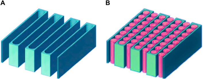
Cold plates are flat metal surfaces with embedded channels for coolant flow. These plates are placed in direct contact with the heat source (e.g., cells or electronic components). The coolant absorbs heat from the source and carries it away, maintaining a consistent battery temperature. Cold plates are commonly used in high-power electronics and electric vehicle battery packs.
Cold plates must be exceptionally flat to ensure efficient contact with heat sources. Any surface irregularities can hinder HR, so achieving a high flatness tolerance is critical for optimal performance.
Regarding manufacturing challenges, selecting materials with low thermal expansion coefficients is crucial to prevent warping during temperature fluctuations in battery operation. Cold plates require precise machining to maintain their flatness, as any deviation could impact heat transfer performance.
Working Principles of Liquid Cooling Systems
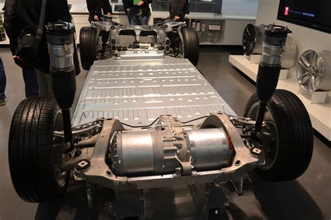
An efficient heat transfer mechanism that can be implemented in the cooling and heat dissipation of EV battery cooling systems for the lithium-ion battery packs, such as a Tesla electric car, can be the following:
- Batteries are cooled by a liquid-to-air heat exchanger that circulates cooling fluids through the battery cells.
- The coolant is a mixture of water and ethylene glycol (similar to antifreeze). This system transfers heat from the battery cells into the air using convection or forced airflow.
- The cooling process involves glycol circulating through pipes within the battery pack, absorbing waste heat generated during charging.
- The glycol flows through an external radiator, releasing heat into the ambient air.
Like automotive engine coolants, EV liquid cooling systems require periodic coolant replacement to maintain thermal efficiency and prevent corrosion or leaks.
Utilization of Latent Heat for Temperature Control
Phase Change Materials (PCMs) store and release latent heat during phase transitions, with common types including paraffin waxes, salt hydrates, and organic compounds. In battery thermal management, PCMs absorb excess heat during temperature rises and release it as the battery cools, maintaining a consistent temperature. They can be embedded within the battery pack or coated on batteries as thermal barriers. During high temperatures, PCMs absorb heat to prevent overheating; as temperatures drop, they release heat to maintain battery stability.
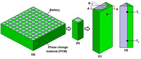
The three main classes of PCMs suitable for cooling are listed below.
- Salt Hydrates
- Salt Hydrates are salts dissolved in water. They have excellent heat-absorbing properties due to their high latent heat of fusion, such as sodium sulfate decahydrate (Glauber’s salt) and calcium chloride hexahydrate.
- n-Alkanes
- n-Alkanes are organic PCMs derived from hydrocarbons. They exhibit phase change behavior at specific temperatures. Paraffin waxes fall into this category. Paraffin waxes have good thermal stability and can absorb and release heat during phase transitions.
- Non-Paraffin Organics
- Non-paraffin organics refer to various organic compounds that are not paraffins. Examples include fatty acids (such as stearic acid) having higher thermal conductivity than paraffins. These non-paraffin organics offer a balance between thermal performance and safety.
Summary and Future Developments for Battery Thermal Management Systems
Exciting times lie ahead for electric mobility! Key takeaways from our article are:
- BTMSs are crucial for ensuring safety, durability, and fast charging in EVs.
- Lithium-ion batteries dominate EVs but risk thermal runaway if not cooled properly.
- Maintaining batteries within an optimal temperature range (0–45 °C) ensures performance and longer lifespan.
- Cooling methods include air cooling, liquid cooling, phase-change materials (PCMs), and heat pipe systems.
- Liquid cooling (direct contact or cold plate) offers the most effective heat removal for high-power EV batteries.
- Liquid cooling systems in EVs use pumps, cold plates, heat exchangers, and piping to circulate coolant, increasing system complexity and overall vehicle weight, but enabling more uniform thermal regulation and higher charge/discharge rates.
- Maintenance of BTMSs requires certified technicians and specialized diagnostic and handling tools, as mishandling of high-voltage packs or glycol-based coolants can lead to electrical hazards or chemical exposure.
- Challenges include potential coolant leaks, component corrosion, and the need for proper recovery and disposal of glycol-based fluids, which are toxic and environmentally sensitive if released improperly.
To summarize the different types of cooling, you can check this table:
Lastly, faster electric vehicle charging is crucial for the mass adoption of electric vehicles. Innovations in charging infrastructure and battery technology aim to significantly reduce charging times for electric cars.
We can expect rapid charging stations to become more widespread, making long trips convenient for electric vehicle owners who will rely on ever-improving battery cooling using liquid coolant.
FAQs
What EV models use liquid or similar cooling?
Many modern EVs use liquid or similar cooling systems for their batteries to manage heat and maintain performance. Tesla Model S/3/X/Y, Jaguar I-Pace, Porsche Taycan, Chevrolet Bolt, and Volt all use liquid-glycol cooling. Hyundai Kona and Ioniq, Kia e-Soul and Niro EV also rely on liquid-cooled packs. BMW i3 uses refrigerant-based cooling integrated with the A/C system.
How does Tesla battery cooling work?
Tesla uses a liquid coolant (water + glycol) that flows through serpentine channels in cold plates, directly contacting battery cells. The coolant absorbs heat and releases it through radiators and heat exchangers, keeping cell temperatures uniform and safe cell temperatures.
How to keep an EV Battery Cool?
Use active cooling (liquid or air), avoid extreme temperatures, limit rapid charging in hot conditions, and park in shaded or ventilated areas.
What are the best practices for battery cooling design?
Optimize coolant flow, maximize transfer surfaces, choose high-specific-heat fluids, minimize pressure drop, and maintain uniform temperature distribution.
How does battery cooling impact battery lifespan?
Effective cooling prevents overheating, reduces degradation, maintains performance, and significantly extends the operational life of Li-Ion batteries.
What are the key methods for thermal management of Li-Ion batteries?
Air cooling, liquid cooling (direct/cold plate), phase-change materials (PCMs), and heat pipe systems.
What is the optimal range in temperature for effective battery cooling?
Lithium-Ion type batteries perform optimally between 0°C and 45°C. This range strikes a balance between factors such as battery efficiency, safety, and battery life.
What techniques can enhance the cooling efficiency of EV batteries?
Increase surface area (e.g., fins), improve coolant flow, utilize high-thermal-capacity fluids, apply phase-change materials, and minimize hot spots.
What is the cost analysis of different battery cooling technologies?
Air cooling is low-cost but less efficient; liquid is more expensive but highly effective; PCMs and heat pipes add material and design costs.


