Structural Vibration: Predicting and Mitigating Dynamic Effects
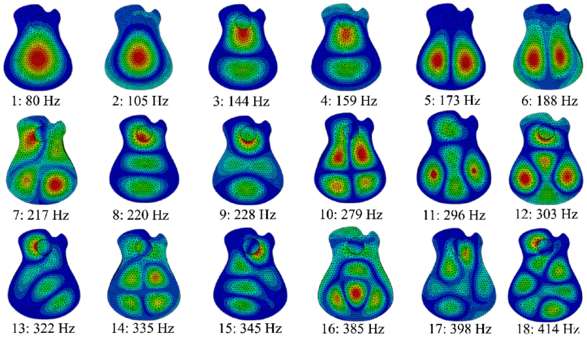
In engineering equipment, structural vibration occurs when forces generated by machines cause the structure to vibrate. This can prompt equipment failure, noise transfer, and safety concerns.
Let's review how mechanical resonance occurs in nature and machinery. We will then move to addressing structural vibration problems. After classifying structural vibration types, we will review some testing and simulation approaches to structural vibration, from FE analysis to deep learning use cases.
Mechanical Resonance in Nature
All objects possess inherent natural frequencies or resonant frequencies (let us denote it as fn) representing the frequencies at which they exhibit a propensity to vibrate. These natural frequencies are governed by the structural characteristics of the object, including its stiffness k, mass m, and damping c.
Mathematically, the natural frequency of an object fn can be expressed using the equation fn = 1 / (2π) * √(k / m) where k is the object's stiffness, and m is the object's mass.
Let us now turn mathematics into a "crystal-clear" example...
Crystal Glass Case Study
When a crystal glass is tapped, it initiates vibrations at its resonant frequency, fn, producing a distinctive sound characterized by a specific pitch. This resonant frequency corresponds to the glass's fundamental mode of vibration.
The above formula for the resonant frequency fn = 1 / (2π) * √(k / m) represents the frequency at which the glass tends to vibrate when excited. The stiffness k of the glass determines how easily it can be deformed or bent by an applied force - a stiffer glass will have a higher resonant frequency. The mass m of the glass determines how much inertia it has, resisting changes in motion - a heavier glass will have a lower resonant frequency. When the glass is tapped, it vibrates at its resonant frequency, producing sound waves in the air. The frequency of these sound waves corresponds to the glass's resonant frequency, resulting in the characteristic pitch of the sound produced.
In mechanical systems, resonance refers to the amplification of sound or other vibrations, including structural vibration. This requires an external periodic force to be applied at a frequency equal to the natural frequency of motion for the object. This is what is called the resonant frequency.
The phenomenon of resonance occurs when the frequency of an external oscillation or vibration matches an object's natural frequency, causing it to vibrate or increasing its amplitude of oscillation.
More and More Oscillations
A simple example is a child learning to go on a swing for the first time. The oscillatory motion of the swing has a natural frequency: when applying a push, i.e., a periodic force at the swing’s eigenfrequency, the amplitude of the oscillation increases, and the child goes higher each time.

Are Eigeinfrequencies Always Beneficial?
Hitting the eigenfrequency of an object isn’t always advantageous!
Going back to the history of design engineering, let us consider the following scenario, hoping no reader will be part of it. Imagine soldiers are marching across a rope bridge in perfect unison.
While this might seem disciplined and orderly, it can have disastrous consequences if they inadvertently match the bridge's eigenfrequency. The synchronized footsteps of the soldiers can induce uncontrollable vibrations in the bridge, potentially leading to its collapse.
To mitigate this risk, soldiers can adopt a technique known as the “breaking step.” By intentionally staggering their footsteps or varying their marching pace, they disrupt the periodic force applied to the bridge, preventing resonance from occurring. This simple adjustment can be crucial in ensuring the stability and safety of the structure.
It's worth noting that even robust bridge designs are susceptible to resonant frequencies, although in rare cases. An example is the Broughton Suspension Bridge, which collapsed in the UK in 1831. Investigations on the collapse (without victims but with several severe injuries) revealed that the synchronized marching of soldiers triggered the collapse, inadvertently matching the bridge's resonant frequency. This incident serves as a reminder of the importance of understanding and mitigating the effects of resonance in structural engineering.
Mechanical Resonance in Machinery
Structural vibration is due to the support structure being mechanically resonant. The term "resonance" is the sound produced by an object when it vibrates at the same rate as the sound waves from another object. It occurs when dynamic forces coincide with the natural frequencies of the supporting structure leading structural to an amplification of oscillations, such that structural elements start to vibrate beyond safe operating limits.
Localized Resonance and Civil Engineering Example
Localized structural resonance occurs when certain structural elements exhibit heightened vibration amplitudes within a specific frequency range. This phenomenon can be observed through vibration measurements, which capture the amplitude of vibrations across different structure frequencies.
Imagine a tall building subjected to wind loads.
As the wind blows, it can induce vibrations in different parts of the structure. At specific frequencies, such as those corresponding to the building's natural modes of vibration, the amplitude of these vibrations may become significantly amplified.
This localized structural resonance can lead to increased motion and potentially affect occupant comfort and safety. Localized structural resonance occurs when specific building elements or components, such as certain floors or sections of the facade, exhibit heightened vibration amplitudes at specific frequencies. For example, a particular floor may resonate at a certain frequency due to its unique stiffness or mass distribution.
At the same time, the entire building may experience global structural resonance, where the overall response of the structure vibrates due to the wind loads. This can involve multiple modes of vibration affecting the entire building, such as lateral sway or torsional motion.

In this example, the vibration amplitude increases at specific frequencies within a certain frequency range, indicating localized structural resonance. Vibration measured using sensors placed at various points on the building helps analyze different frequency bands.
Addressing the Vibration Problem
It is costly to "after the fact" modify a structure to fix a vibration problem. However, structural vibration can be preemptively alleviated thanks to the preliminary design.
How can we control high levels of vibration?
In the design phase, a structural vibration analysis field testing of specific areas of the deck or platform should be undertaken. Structural engineers should isolate it from the structure to minimize structural response in such a case.
Types of Structural Vibration
We have seen that although vibration can have positive consequences, like in musical instruments, it is a primary concern to void it in many industrial situations.
It is essential to understand and classify the different types of vibration so that we can recommend the best-placed solution. Despite the diversity in vibration types, the common thread lies in the repetitive motion that affects the mechanical properties of structures.
By employing fundamental structural models, measures, and analysis techniques, it is possible to characterize and manage vibration, ensuring the integrity and performance of industrial systems.
Vibration Categories
Excessive noise and vibration pose significant challenges in factory and industrial settings. Implementing effective measures to mitigate these issues and ensure a safe and productive work environment is imperative.
One approach to addressing noise vibration is to enclose noisy machinery, reducing the spread of noise throughout the facility. Additionally, it is essential to evaluate machine usage and implement proper management practices to prevent overuse.
Structural vibration manifests in different forms, each with distinct characteristics and implications. Free vibration, for instance, occurs naturally in structures following an impact or displacement. This behavior can be assessed through the inherent properties of the structure, offering insights into its mechanical feedback.
In contrast, forced vibration occurs when an external force continuously drives a structure into vibrational motion. The amplitude of the forcing function directly influences the vibration level, with the relationship governed by the structural properties.
Sinusoidal vibration, although uncommon, provides a valuable engineering tool for understanding complex vibrations by isolating them into single-frequency oscillations.
Conversely, random vibration, such as that experienced while driving a car, arises from a combination of factors and is characterized by statistical parameters, making precise prediction of future behavior challenging.
Rotating imbalance represents another prevalent source of vibration, where an unbalanced machine part induces vibration throughout the structure. Properly balancing the machine is crucial to minimizing vibration in rotating equipment.
Structural Vibration Analysis and Testing
Structural vibration analysis and testing are crucial in aerospace, automobile manufacturing, and electronics industries. They ensure reliability, safety, and performance.
Critical Components of Structural Vibration Analysis
Utilization of Finite Element Analysis: Engineers use specialized software to simulate complex dynamic loads and analyze structures with a dynamic FE model.
Identification of Natural Frequencies and Mode Shapes: Determining natural frequencies and mode shapes helps understand how structures respond to vibrations.
Vibration Analysis and Response Assessment: Engineers evaluate how structures handle dynamic loads to ensure they meet requirements.
Comprehensive Assessment of Analysis Results: Reviewing analysis results, including acceleration and stress, is essential for verifying structural integrity.
Challenges and Considerations in Structural Vibration Analysis
Structural vibration analysis faces numerous challenges, particularly when assessing the dynamic behavior of machinery and equipment. These challenges often stem from the complex nature of industrial systems and the interplay between various components. Engineers must contend with factors such as nonlinearities, material properties, and boundary conditions, all of which can significantly influence the vibrational behavior of structures.
Furthermore, accurately modeling and predicting the dynamic behavior of large-scale systems pose additional hurdles, requiring sophisticated analytical techniques and computational resources. Еnsuring the validity and accuracy of simulation results amidst uncertainties and variability also presents ongoing challenges in structural vibration analysis.
Additionally, considerations extend beyond the intrinsic characteristics of the system itself to encompass factors such as environmental conditions and operational constraints.
Variations in temperature, humidity, and external loads can introduce additional complexities, necessitating robust methodologies for mitigating their effects on structural dynamics.
Furthermore, compliance with industry standards and regulations adds another layer of complexity to structural vibration analysis, requiring meticulous adherence to established guidelines and protocols.
Significance of Incorporating Foundation Dynamics
Recognizing the interplay between a system and its foundation is paramount in structural vibration analysis. The foundation is the anchor point for machinery and equipment, providing structural support and stability. Neglecting to account for the dynamics of the foundation can have profound implications for the reliability, safety, and performance of industrial systems.
For instance, improper foundation design or inadequate structural support can lead to excessive structural vibration, resonance phenomena, and structural instabilities, compromising operational efficiency and posing safety hazards.
Moreover, the foundation acts as a conduit for transmitting vibrational energy between the system and its surroundings, influencing the overall vibrational characteristics of the structure.
Therefore, accurately characterizing the foundation dynamics and understanding their impact on the system's behavior is essential for ensuring the robustness and longevity of industrial equipment.
By incorporating foundation dynamics into structural vibration analysis, engineers can identify potential risks, optimize design parameters, and implement mitigation strategies to enhance the reliability and safety of industrial systems.
In summary, structural vibration analysis and testing are critical for optimizing the performance, safety, and reliability of various industries.
Moving Ahead of Static Analysis
Dynamic vibration studies involve the analysis of vibration signals and responses of structures under varying dynamic loads. This includes studying the natural frequencies, mode shapes, damping characteristics, and resonance phenomena of structures subjected to dynamic forces. Engineers use dynamic vibration studies to understand how structures behave under real-world conditions, such as machinery operation, seismic events, or wind-induced vibrations.
On the other hand, static vibration studies focus on analyzing the behavior of structures to static loads or forces. This typically involves studying structures' deformation, stress distribution, and stability under static loading conditions. Static vibration studies are valuable for assessing the structural integrity and performance of components subjected to steady loads, such as dead loads, live loads, or thermal loads.
Modal Analysis
In engineering analysis, various methodologies are employed to comprehend the behavior of structures under different conditions. While quasi-static analysis and dynamic analysis offer insights into system responses under specific loading conditions, modal analysis takes a different approach, providing a holistic understanding of a system's dynamic properties.
Distinguishing Modal Analysis From Quasi-Static and Dynamic Analyses
The quasi-static analysis involves applying loads at an extremely slow rate, eliminating acceleration effects. This approach allows for a simplified examination of the system, often assuming negligible acceleration.
On the other hand, dynamic analysis considers the influence of acceleration, providing a detailed exploration of how the system behaves under varying dynamic loads.
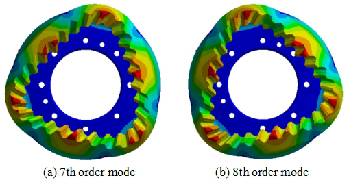
Modal Analysis: A Gateway to System Response Limits
The modal analysis approach takes a broader perspective, aiming to elucidate the fundamental limits of a system's response. Instead of focusing on specific load scenarios, modal analysis delves into the inherent dynamic characteristics of the system. For instance, it addresses questions like: Given a particular input, such as a load with specific amplitude and frequency, what are the system's response limits? When does the system reach its maximum displacement?
Understanding Modal Analysis in the Frequency Domain
The modal analysis approach primarily operates in the frequency domain, offering a comprehensive view of a system's dynamic behavior. It involves mechanically exciting the structure under study to target its mode shapes and recording structural vibration data using a network of sensors.
Central to modal analysis is the concept of normal modes, which represent patterns of motion wherein all parts of the system move sinusoidally with the same frequency and phase relationship. The frequencies associated with these normal modes are termed natural frequencies or resonant frequencies, indicating the inherent vibrational characteristics of the system.
FPSO Case Study
In this hypothetical scenario, we explore the potential challenges and solutions related to structural vibration analysis on a Floating Production Storage and Offloading (FPSO) vessel.
An FPSO typically represents a converted or purpose-built vessel equipped with processing facilities for oil and gas production, storage tanks, and offloading systems. These vessels are designed to float and operate in offshore locations, where they receive hydrocarbons from subsea wells, process them onboard, store the produced oil and gas, and subsequently offload it to shuttle tankers or pipelines.
FPSOs are essential assets in offshore oil and gas operations, but they can face structural integrity issues due to vibrations induced by environmental factors and machinery operations. While this scenario is hypothetical, it underscores the importance of structural vibration analysis in maintaining the safety and reliability of FPSO installations.
By leveraging advanced testing, modeling, and monitoring techniques, operators can proactively address vibration-related challenges and optimize asset performance in offshore environments. Continued advancements in structural dynamics analysis will further enhance the resilience and longevity of FPSO assets in the future.

Imagine an FPSO operating in a demanding offshore environment with high waves, strong currents, and harsh weather conditions. Concerns arise regarding excessive vibrations compromising the vessel's structural integrity, safety, and operational efficiency. A comprehensive structural vibration analysis is proposed to address these concerns, incorporating modal testing, finite element analysis (FEA), and operational monitoring.
The envisioned modal testing involves measuring and analyzing the FPSO's dynamic characteristics, such as natural frequencies and mode shapes. Advanced instrumentation, including accelerometers and modal exciters, would be utilized to conduct tests under different operational conditions. Modal analysis techniques would then be applied to identify critical vibration modes and potential resonance issues.
FEA is then employed to simulate the FPSO's structural response to dynamic loads. A detailed structural model of the vessel, including its hull, topside modules, and mooring system, would be created using FEA software. Various loading scenarios, such as wave-induced motions and machinery vibrations, would be simulated to assess structural performance under dynamic conditions.
Operational monitoring would involve real-time data acquisition to track the FPSO's vibration levels during operation. Remote sensing systems, such as vibration sensors and strain gauges, would be installed at critical locations on the vessel. Data analytics techniques would analyze vibration trends and detect anomalies, enabling proactive maintenance and risk mitigation.
Results and Recommendations: Based on the envisaged analysis, potential issues affecting the FPSO's structural integrity and operational performance will be identified. Recommendations would be proposed to mitigate vibration risks, such as structural modifications, equipment upgrades, and optimized operational procedures. A monitoring and maintenance program would also be established to ensure ongoing vibration management and asset reliability.
Implications for Real World Structures
Modal analysis, with its ability to reveal the dynamic properties of real-world structures, holds significant implications across various domains, from engineering to societal impacts.
In today's technologically driven world, modal analysis benefits from advancements in sensing technologies (IoT) and computational methods. High-resolution sensors and sophisticated data analysis techniques enable engineers to characterize the modal behavior of structures precisely, enhancing their understanding and enabling more accurate predictions of performance under dynamic conditions. This technological prowess facilitates design optimization and structural integrity assessment and supports the development of innovative materials and construction techniques.
In infrastructure governance, modal analysis is critical in ensuring safety regulations and standards compliance. Regulatory bodies rely on modal analysis insights to evaluate the resilience of bridges, buildings, and other critical infrastructure assets. By providing quantitative assessments of structural performance, modal analysis informs policy decisions regarding maintenance priorities, investment strategies, and disaster preparedness measures. Moreover, it fosters transparency and accountability in public infrastructure projects, bolstering public trust and confidence in governmental institutions.
The implications of modal analysis extend beyond technical considerations to encompass broader societal impacts. By enhancing the safety and reliability of infrastructure systems, modal analysis contributes to communities' well-being and quality of life. It enables the design of resilient structures capable of withstanding environmental hazards, natural disasters, and other unforeseen events.
The Future of Structural Vibration Studies - Deep Learning?
By coalescing decades of FEA and testing data into ordered databases, many corporations are AI-ready to deploy, thanks to the specific workings of Deep Learning, a novel approach that can simulate quite accurately, in a few ms, the high fidelity Finite Element software that would otherwise require minutes or hours of number crunching time, plus months or years of specific training!
This exciting new perspective has been explored by us elsewhere in the articles we invite you to peruse.

Mathematical Appendix - FRF in Structural Vibration Analysis
The frequency response function (FRF) is a cornerstone in structural dynamics and vibration analysis, delineating the relationship between input force and system response across various frequencies.
In mathematical terms, the FRF is represented as a complex function, denoted by H(ω), where ω represents angular frequency.
(note: In structural dynamics and vibration analysis, the angular frequency is commonly used to describe the oscillations or vibrations within the system. It is related to the regular frequency f (in Hertz) through the equation: ω=2πf - so ω represents the frequency in terms of radians per unit time, while f represents the frequency in terms of cycles per unit time, i.e., Hertz)
The FRF can be expressed as the ratio of the output response to the input force in the frequency domain:
H(ω)=F(ω) X(ω)
where X(ω) is the output response and F(ω) is the input force in the frequency domain.
The complex FRF consists of magnitude and phase components:
- The magnitude of the FRF, denoted ∣H(ω)∣, represents the amplification or attenuation of the input signal at each frequency.
- The phase of the FRF, denoted∠H(ω), indicates the time delay or phase shift between the input and output signals.
Therefore, the FRF encapsulates the system's behavior across frequencies, including amplification/attenuation and phase shift, utilizing the framework of complex numbers.
Using the complex notation c=a+ib, where a represents the real part and b represents the imaginary part, the FRF can be expressed as:
H(ω)=∣H(ω)∣⋅e^i∠H(ω)
So, in terms of the real and imaginary parts:
∣H(ω)∣=a²+b² and ∠H(ω)=arctan(ab)
The FRF provides valuable insights into the dynamic behavior of a system across different frequency ranges. By analyzing the FRF, engineers can identify the system's resonant frequencies, damping characteristics, and overall dynamic performance.
FRFs are commonly used in various engineering applications, including structural analysis, structural vibration testing, and control system design. They play a crucial role in predicting and optimizing the response of structures and mechanical systems to external excitations, ensuring their reliability, safety, and performance.
FRF and Its Relationship to FEA in Structural Vibration
FRF and Finite Element Analysis (FEA) are important tools used in structural dynamics and vibration analysis, but they serve different purposes and are applied in other contexts:
- FRF is a mathematical representation of the dynamic behavior of a system in the frequency domain. It describes how the system responds to an applied force or excitation at various frequencies. The FRF is typically determined experimentally through modal testing or analytically through numerical methods.
- On the other hand, FEA is a computational technique used to analyze the structural response of complex systems under various loading conditions. It discretizes the structure into finite elements and applies numerical methods to solve for the structure's displacements, stresses, and strains.
While FRF and FEA are distinct methods, they can complement structural analysis. FEA results can be compared with experimental FRF data to validate the accuracy of the numerical structural model. If the FEA results closely match the experimental FRF measurements, it provides confidence in the predictive capabilities of the finite element model.
FEA can be used to perform modal analysis, where a structure's natural frequencies, mode shapes, and damping properties are determined numerically. These various modal parameters and properties can then be used to calculate the mode shape of the FRF analytically and compare it with experimental measurements.
By analyzing the FRF of different design configurations, engineers can identify optimal geometries and material properties that minimize control structural vibration.
Mathematical Appendix - What Is an Eigenvalue?
When we model a mechanical object as a system of connected springs, its output as a function of an applied input can be represented as:
k⋅x=y
Here, k acts as a scaling factor, similar to the spring equation where k represents the spring stiffness, x denotes the spring displacement, and y represents the applied force.
For a more generalized 3D system, we extend this representation into matrix form:
[K]{x}={y}
Here:
- {x} is a displacement vector,
- {y} is a force vector, and
- [K] is the stiffness matrix, serving as a scaling factor.
In certain scenarios, the system might satisfy:
[K]{x}={y}⇒[K]{a}=L⋅{a}
L represents the eigenvalues, and {a} denotes the eigenvectors corresponding to the eigenvalues L.
Understanding Eigenvectors and Eigenvalues:
Vectors represent multi-dimensional quantities characterized by both magnitude and direction, often depicted as arrows. When vectors undergo a linear transformation, they undergo rotations, stretches, or shears.
Eigenvectors of a transformation are those vectors that undergo only stretching without rotation or shear. The corresponding eigenvalue is the factor by which an eigenvector is either stretched or compressed along its direction (for positive eigenvalues) or in the opposite direction (for negative eigenvalues).
This understanding provides insights into how the system's behavior is influenced by its inherent properties, encapsulated by eigenvectors and eigenvalues.


