What Is Fluid-Structure Interaction? And How to Solve FSI Issues
Intuitively, solid materials, walls, or obstacles influence fluid flow. However, a surrounding fluid flow can also affect a movable or deformable structure. Interestingly, there are also more complex problems in two-way interaction situations, where the fluid flows influence structures by deforming them with large displacements, and structural response causes changes in fluid motion.

This article will explore situations where solids and fluids can influence each other through one-way and two-way fluid-structure interaction.
What is a Fluid-Structure Interaction Problem?
The interaction between fluid flow and solid structures involves complex simultaneous phenomena such as the dynamics of fluids, solid mechanics, and thermodynamics.
The coupling of these phenomena can result in various outcomes, such as vortex-induced vibration or aeroelasticity.

Vortex-induced vibration manifests itself in many different branches of engineering, from cables to heat exchanger tube arrays.
Aeroelastic effects are common in aerospace structures because they must be lightweight while enduring large aerodynamic loads.

A flow field characterizes laminar and turbulent flows, while deformation and stress fields characterize the solid structure. Thus, solid deformation and stress fields can affect a fluid flow, and the flow field can affect a solid.
From a practical point of view, how can two different software communicate, and what is the relevance of fluid-structure interaction problems for various industries? Read this article to learn more!
We will describe engineering cases, move on to aerospace examples, and delve into the physics and simulation software. We will conclude with the potentially revolutionary impact of AI on fluid-structure interaction simulation.
While of interest, conjugate heat transfer is now so easy to implement in standard CFD codes that it will not be dealt with in the article where we will instead focus on two-way simulation where FEA simulations and CFD simulations exchange data.
Fluid-Solid Interactions: Case Histories
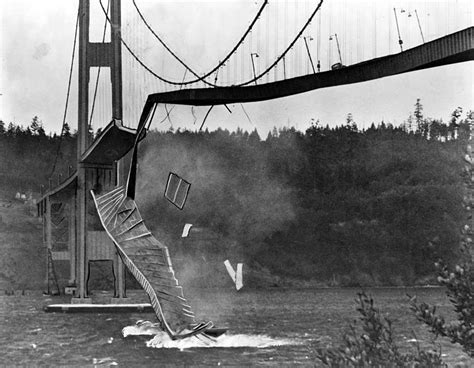
The collapse of the Tacoma Narrows Bridge highlighted the importance of fluid-structure interaction in large structures, leading to advancements in engineering practices. Today, bridges and skyscrapers exposed to wind are designed to be more resistant to natural forces.
Willis Tower is one of the tallest buildings in the United States. Engineers used a bundled tube construction method to ensure stability and prevent excessive sway caused by high wind speeds. This technique allows for more oversized windows and natural light while evenly distributing the building's weight across its perimeter.
Engineers addressed fluid-structure interactions using design features such as the building's square shape, rounded corners, and tapering shape to minimize wind effects. They also installed a tuned mass damper system on the 99th floor.
FSI in Aerospace Biomedical and Automotive Engineering
Fluid-structure interactions are critical in several industrial applications in aerospace and automotive, ranging from designing aircraft wings or helicopter rotors to automotive body panels and engine components.
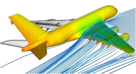
In aerospace, fluid-structure interaction is significant for the design of wings and rotor blades. The deformation of the wing or rotor blade due to aerodynamic loads can affect the flow of air around the structure, which can, in turn, affect the lift and drag forces acting on the structure. FSI is key in the shape optimization of wings or turbine blades to improve aerodynamic performance and reduce the risk of structural failure. Fluttering is a significant fluid-structure interaction problem in aerospace. It is a dynamic instability phenomenon where aerodynamic forces are coupled with the natural vibration modes of the structure, leading to potentially catastrophic oscillations. Fluttering is a significant concern for wings, rotor blades, and other aerodynamic surfaces. Engineers can predict flutter conditions through two-way data exchange simulations.
Automotive engineering research supports a competitive industry where realistic simulation approaches lead to generative design. In automotive applications, fluid-structure interaction and conjugate heat transfer are essential for designing body panels and engine components with complex shapes and physics, subject to conjugate heat transfer or FSI in the strict sense of this article. The interaction between the flow and the structure can affect the vehicle's aerodynamics, thermal performance, and the engine components' durability. FSI helps designers optimize the shape and stiffness of body panels to reduce drag, improve fuel efficiency, and optimize an engine cooling system.
FSI studies can help understand heart valve dynamics.
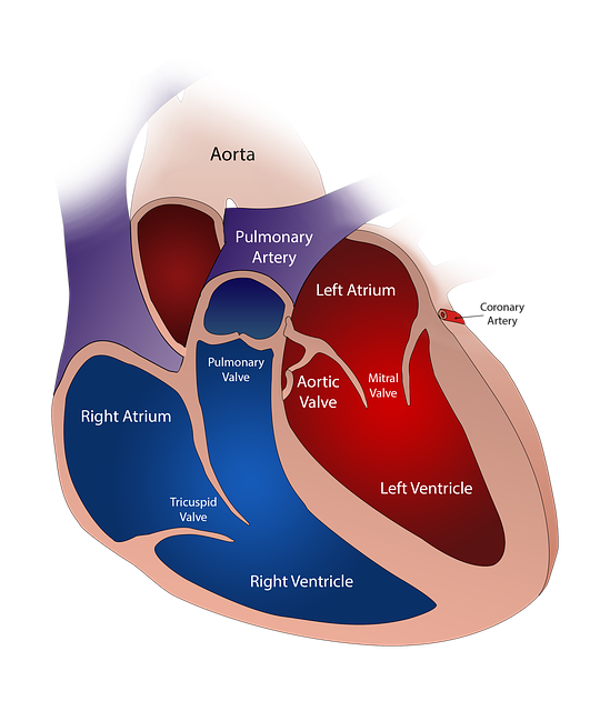
Blood pressure is a critical parameter in data exchange as it influences the forces exerted on the valve leaflets. Pressure modeling allows for the simulation of the mechanical environment experienced by the valves. Also, blood pressure varies with the cardiac cycle, creating cyclic loading conditions on the valve. FSI models account for these variations, allowing for assessing valve performance under realistic physiological conditions and contributing to developing devices that protect blood flow patterns.
Specifically, understanding the advantages and limitations of rigid versus flexible heart valves through FSI models enables researchers to design more effective prosthetic valves:
- Rigid valves are characterized by their durability and longevity. FSI models help identify potential issues such as high shear stress, blood damage (hemolysis) due to the rigid structure, and the risk of thrombosis.
- Flexible valves include bio-prosthetic valves made from biological tissues, which offer better hemodynamic performance and lower thrombosis risk. FSI can optimize their design by evaluating their deformation under different physiological conditions, ensuring minimal stress concentration ( a crucial factor for preventing tissue fatigue and failure).
How to Simulate Fluid-Structure Interaction: One-Way Simulation
The fluid-structure interaction (FSI) simulation field has evolved significantly over the past few decades.
Traditional methods were based on simplified assumptions, while recent methods are more accurate and reliable. FSI coupling offers computational advantages and flexibility but can also present drawbacks, including cumbersomeness in information exchange, reduced precision, and stability challenges.
How to Do It One-Way, in Two Steps!
First, ensure your CFD simulation has a clear interface between the fluid and solid domains! This interface is typically defined by the surfaces of the FEA mesh that are in contact with the fluid. Identify and select the boundary or boundaries on the CFD mesh that represent the interface between the fluid and solid domains. This could be done visually by selecting the surface corresponding to the solid object in your simulation domain. : Once you have selected the interface boundary, extract the pressure data associated with that boundary. In ParaView, for example, you can use the "Extract Surface" filter to isolate the selected boundary and then extract pressure values associated with that surface.
The next step is to export the extracted pressure data into a format compatible with your FEA software. A common format is CSV (Comma-Separated Values). Ensure that the exported file contains the necessary information, typically including each point's coordinates (x, y, z) on the interface boundary and the corresponding pressure values (P). Before proceeding to the FEA simulation, verify the exported data to ensure that it accurately represents the pressure distribution on the interface boundary. You can do this by visualizing the exported data or spot-checking pressure values at specific points.
One-Way Coupling Advantages and Limitations
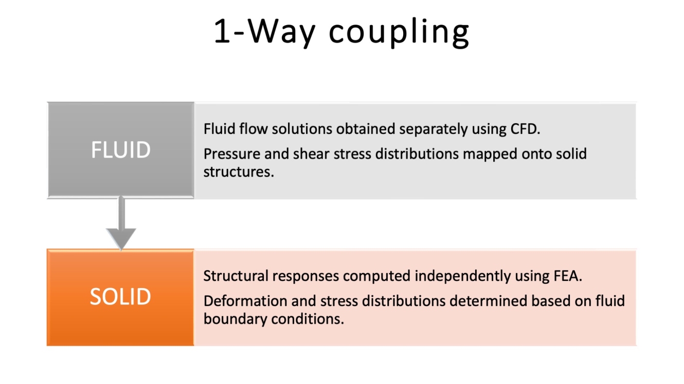
One-way coupling (loosely coupled method) involves solving the flow and structural equations separately and then coupling the two solutions in one iteration.
In this approach, the fluid flow affects the structure, but the feedback from the structural response to the fluid flow is not considered in the same iteration. This method simplifies the computation and reduces the complexity of the problem.
However, it has significant limitations.
Results can lack accuracy because the structural response does not influence the fluid flow within the same iteration, especially in critical dynamic interactions. This approach's decoupled nature can lead to convergence issues and inaccuracies in capturing the actual behavior of the interacting systems.
We may conclude that one-way coupling is suitable for scenarios where the interaction between the flow and the structure is weak or high precision is not essential.
More in detail, the one-way numerical analysis workflow is the following.
Step 1 — Fluid Flow Solution with CFD: The fluid flow equations are first solved with computational fluid dynamics software to obtain the pressure and shear stress distributions on the structure's surface.
Step 2 — Mapping Pressure and Shear Stress: The fluid solution's computed pressure and shear stress are mapped onto the solid structure's surface as boundary conditions.
Step 3—Structural Response with FEA: Using FEA software, the structural equations are solved using the fluid flow's applied boundary conditions (BCs) to determine the structure's deformation and stress distribution.
Two-Way Data Exchange
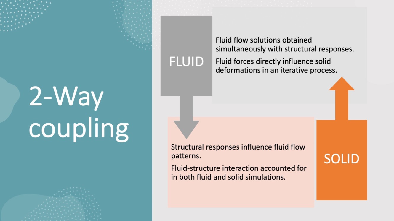
In recent years, several computational methods, including fully coupled solvers, immersed boundary methods, and reduced-order modeling techniques, have been developed to simulate FSI, mainly with a two-way simulation approach.
Implicit or Explicit FSI
Choosing between explicit and implicit coupling methods is critical to 2-way FSI simulations. Explicit coupling is sequential and simpler but less stable, while implicit coupling is simultaneous, more stable, and computationally intensive. This choice is typically made within the simulation setup in integrated FSI software, tailored to the specific interaction dynamics of the solved problem.
The choice between explicit and implicit coupling methods is embedded within the simulation setup in integrated FSI software solutions provided by commercial CAE vendors. These software tools provide interfaces to define how the fluid and structural solvers interact, allowing users to select the appropriate coupling strategy based on their simulation's specific requirements.
Implicit Coupling is essential for highly coupled problems where structural deformations significantly affect the fluid flow, such as in aeroelasticity.
In implicit coupling, the fluid and structural solvers operate simultaneously within each time step, solving the coupled equations iteratively until convergence is achieved. This method balances fluid and structural responses at each time step. We can get greater stability and the ability to handle larger time steps, making it suitable for strongly coupled interactions. This comes at a cost. The cost is an increased complexity and higher computational cost due to the iterative solution process. Implicit coupling is suitable for less tightly coupled interactions where the impact of structural deformation on fluid flow is moderate.
In explicit coupling, the fluid and structural domains are solved sequentially within each time step. The fluid solver computes the fluid forces and passes them to the structural solver, then calculates the structural response. The updated structure is then used in the next fluid computation.
While this method is simpler and has a lower computational cost per time step, we can meet potential instability and the need for smaller time steps to ensure accuracy and stability.
Mathematics of Explicit and Implicit FSI
As a final mathematical comparison - in explicit FSI, we can have the following continuum equations governing the interaction between fluid (denoted with a superscript ᶠ) and solid (denoted with ˢ):
- Fluid Equation: ∂𝐮ᶠ / ∂𝑡 + (𝐮ᶠ ⋅ ∇)𝐮ᶠ = -1/𝜌 ∇𝑝ᶠ + 𝜈∇²𝐮ᶠ + 𝐟ᶠ
- Structure Equation: 𝑀ˢ ∂²𝐮ˢ / ∂𝑡² + 𝐾ˢ 𝐮ˢ = 𝐟ˢ
- Explicit Coupling: 𝐟_fluid-struct = 𝑔(𝐮ᶠ, 𝐮ˢ)
(please note that 𝐟ᶠ represents external forces acting on the fluid "f" (ᶠ), such as gravitational forces or forces applied from boundaries; 𝐟ˢ represents external forces acting on the structure "s" (ˢ) - these structural external forces could include gravitational forces, applied loads, or any other external forces acting on the structure that are not accounted for by the internal dynamics described by the mass 𝑀ˢ and stiffness 𝐾ˢ matrices).
In implicit FSI, we can have the following equations governing the interaction:
- Fluid Equation: ∂𝐮ᶠ / ∂𝑡 + (𝐮ᶠ ⋅ ∇)𝐮ᶠ = -1/𝜌 ∇𝑝ᶠ + 𝜈∇²𝐮ᶠ+ 𝐟ᶠ+ 𝐟_fluid-struct
- Structure Equation: 𝑀ˢ ∂²𝐮_s / ∂𝑡² + 𝐾ˢ 𝐮_s = 𝐟ˢ + 𝐟_struct-fluid
The implicit coupling is given by 𝐟_fluid-struct, which represents the forces exerted by the fluid on the structure, and 𝐟_struct-fluid, which represents the forces exerted by the structure on the fluid.
Rigid Body Motion with Arbitrary DoFs in CFD
In the Computational Fluid Dynamics approach, studying rigid body motion with arbitrary Degrees of Freedom (DoFs) is essential in simulating and analyzing complex fluid-structure interaction problems such as valves or yachts. Rigid body motion refers to the movement of a solid object through a flow domain without undergoing any deformation or strain.
When analyzing fluid flows around bodies, it is essential to consider all possible degrees of freedom of the moving structure to capture its movement and interaction with the surrounding fluid accurately. Traditional computational fluid dynamic simulations often assume restricted degrees of freedom, such as translational and rotational motions along predefined axes.
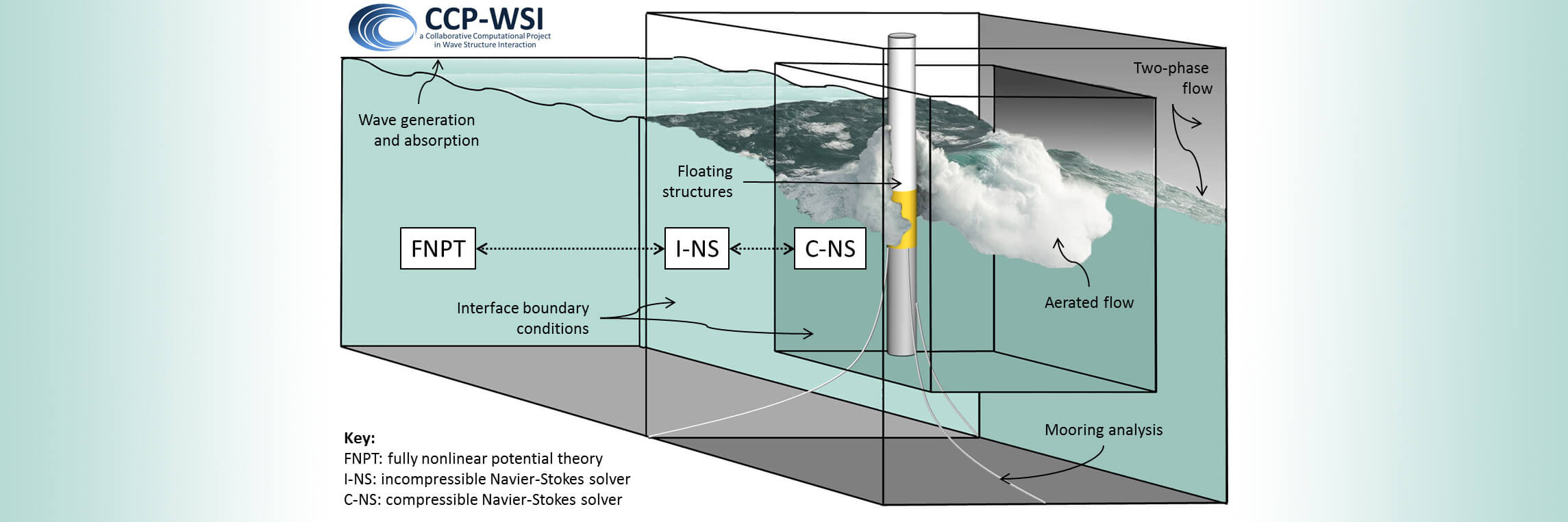
In real-world scenarios, rigid bodies can have various degrees of freedom (DoFs); simulating it in CFD requires overset grids or coupling a computational fluid dynamic solver with a rigid body dynamics solver. Applications range from analyzing aircraft maneuvering to studying underwater vehicles or internal flows with valves. These simulations provide insights for designing and optimizing some mechanical engineering systems subjected to fluid flow.
Immersed Boundary Method
This method solves the flow equations using a fixed Cartesian grid, with the structure represented by an immersed boundary embedded in the grid.
The immersed boundary is discretized using Lagrangian elements, such as springs or beams, interacting with the CFD grid points through a force term.
An advantage is the flexibility in handling complex geometries; also, it is computationally efficient since the fixed Cartesian grid simplifies the computational mesh.
Other Methods (SPH)
Smoothed Particle Hydrodynamics (SPH) is a computational method used to simulate the behavior of fluids and solids. Recently, there has been a growing interest in using SPH models to solve Fluid-Structure Interaction (FSI) problems. Two main approaches have emerged in this context: the first approach involves coupling the SPH solver with a mesh-based structure solver while the second approach focuses on developing a purely Lagrangian particle method to handle both the fluid and structure components within the same particle-based framework.
Fully Coupled Solvers
Fully coupled solvers are modeling approaches that simulate fluid-structure interaction. These solvers solve governing equations concurrently without partitioning the system into different software that runs sequentially or serially.
The equations governing fluids and solid structure are solved, respectively. BCs accomplish the coupling: the velocity at the structure equals the structural velocity, and the fluid pressure balances the everyday stress at the structure interface at the boundary. These BCs provide information exchange between the fluid and structural domains.
One disadvantage of fully coupled solvers is their high computational costs, particularly for large-scale fluid and structural simulations. However, recent advancements in computational hardware and algorithms make fully coupled solvers more practical for complex FSI simulations.
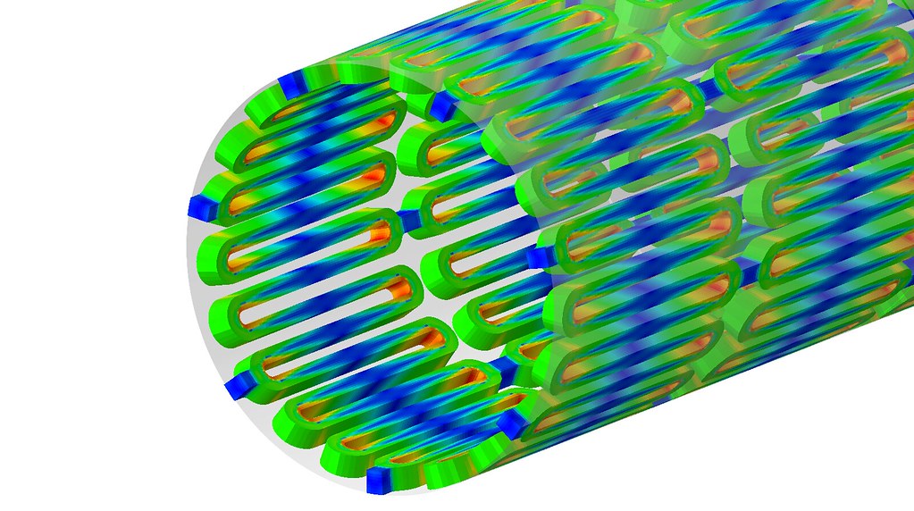
The image shows the two-way coupling between a 9-parameter Mooney-Rivlin hyperelastic model for the solid structures and a transient, isothermal, incompressible, and laminar (low Reynolds number) fluid model. Modeling approaches are based on specific physics and materials, so in this case, density 𝜌 represents the blood density in the fluid and the arterial wall density in the solid structure.
Fluid-Structure Interaction with Deep Learning
In FSI simulations, the mechanics of fluids and solids are combined to analyze their interaction. Traditionally, these simulations use computationally expensive solvers, but recent advancements in deep learning have opened up possibilities for using neural networks as surrogate models. This raises the question: Could deep learning replace fluid and structural simulations in FSI?
Deep learning shows promising results in surrogate modeling, which approximates complex functions or processes based on input-output data in engineering and scientific domains. The NC platform by Neural Concept, a surrogate of CFD, can deal with any complex geometry, either from CAD or FEA-computed deformations.
Deep learning surrogates have the advantage of a faster response than CFD and FEA solvers, thus complementing purely physics-based numerical methods.
CFD simulations involve solving the Navier-Stokes equations, which can be computationally intensive. Deep learning surrogates offer a faster and more cost-effective option for specific applications, provided a representative dataset for training is available.
Deep Learning prediction instead of CFD in an FSI analysis can be pretty convenient. Let us see why and how this can happen.
Using a trained deep-learning surrogate can make the fluid-structure FSI simulation more efficient. In a wing FSI case, the structural solver simulates the wing's deformation using traditional methods based on aerodynamic loads provided by the deep learning surrogate for CFD. The deep learning model predicts the aerodynamic force acting on the wing based on structural deformation and data provided by the FEA solver, creating an iterative process that accurately captures dynamic interactions.
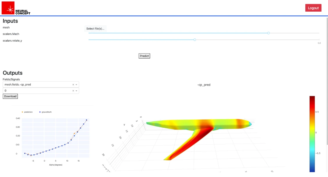
The advantages are evident in terms of computational burden and ease of use.
A deep learning surrogate for CFD, such as the Neural Concept platform (NC) trained with a CFD dataset, can significantly reduce the computational burden associated with traditional computational fluid dynamic simulations. Once trained with CAE or even experimental data, the surrogate model performs very fast predictions based on the newly deformed shape of the solid domain (considered a CFD boundary). NC can provide rapid predictions of fluid forces, leading to faster overall FSI simulations.
Conclusion - Future Scenarios
We have shown how FSI helps understand and improve the design of various systems, such as heart valve replacements, aerospace components, and automotive designs. These studies use simulations to predict how pressure and other forces exerted by fluids affect the solid structure and its deformation - and vice versa.
As a step forward, integrating Finite Element Analysis with a Deep Learning surrogate for Computational Fluid Dynamics in FSI presents a powerful solution to enhance efficiency and significantly reduce computational costs.
This approach leverages the strengths of both methodologies, enabling engineers to gain highly realistic insights into complex fluid-structure interaction problems. Thus, it can drive advancements in aerospace design, automotive engineering, biomedical engineering, and civil infrastructures.


