Full Guide to Hydrodynamic Simulation: Theory to Application
Regardless of type, vessels share a common factor — they must traverse through a fluid medium: water.
When analyzing how a vessel can travel through water, the primary focus is on hydrodynamic flows and the forces exerted on the submerged portion of the vessel.
Those forces significantly impact stability, propulsion, and overall performance.
In this article, we'll analyze the main hydrodynamic forces and the aerodynamic contributions that are relevant for special vessels such as sails. Also, we'll give some guidelines for CFD software marine application.
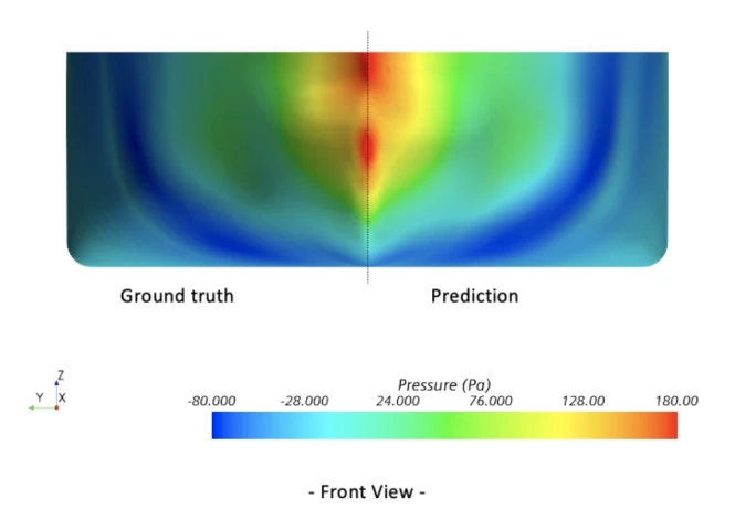
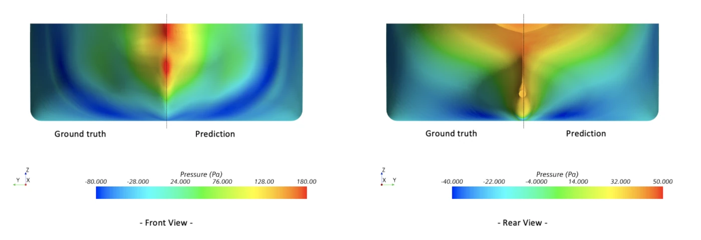
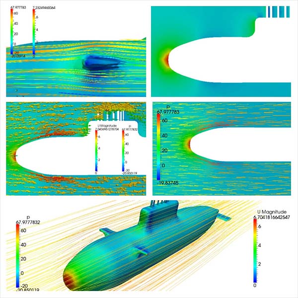
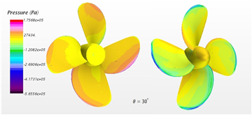
We'll see how AI can revolutionize marine engineering by making complex CFD simulation software usable to produce predictions very similar to the original CFD simulation (ground truth) — see the figure for yourself.
But before understanding how to tackle hydrodynamical simulations, we'll investigate the physical laws related to vessel dynamics for dislocating and planning hulls.
What Are the Forces on a Vessel?
Buoyancy and Gravity
The principle of buoyancy is well known: when a boat is placed in water, it displaces an amount of water equivalent to its weight. The displaced water exerts an upward force, buoyancy, which counters the gravitational force acting on the boat, preventing it from sinking.
Hydrodynamic Drag
As a boat moves through the water, it encounters resistance known as hydrodynamic drag. This resistance arises due to the friction between the boat's hull and the water. Boat designers meticulously shape the hull to minimize friction, reducing drag and enhancing efficiency.
Propulsion
To propel forward, boats necessitate a source of propulsion, either a natural source or by an engine. Sailboats, for instance, harness the wind's force on their sails, creating lift. Conversely, powerboats employ engines and propellers to generate thrust, propelling the boat through the water. Balancing these forces is crucial to achieve efficient and controlled motion.
How Do Forces Compose?
Forces acting on boats can be categorized into two main groups: aerodynamic and hydrodynamic forces on the boat, i.e. forces above and below the waterline. These forces interact dynamically to determine a boat's behavior and performance.
Aerodynamic Forces
Aerodynamic forces come into play when considering the boat's components above the waterline. In the context of sailboats, the primary aerodynamic force is lift generated by the sails:
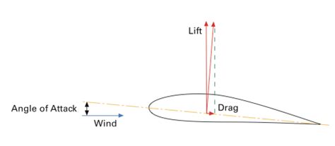
- Lift: As wind flows over the curved sail surfaces, it creates a pressure differential, resulting in lift. Lift propels the boat forward, harnessing wind energy for propulsion.
- Drag: Alongside lift, aerodynamic drag is a consideration. Drag opposes the boat's forward movement and results from air resistance on sails and above-water components.
Hydrodynamic Forces
Below the waterline, vessels experience hydrodynamic forces vital for stability and control:
- Buoyancy: A hydrodynamic force acting vertically upward. It supports the vessel's weight and prevents it from sinking.
- Hydrodynamic Drag: Like aerodynamic drag, hydrodynamic drag opposes the vessel's motion but originates from the interaction between the hull and water.
- Lateral Resistance: Sailboats depend on lateral resistance, generated by the keel or centerboard shape, to counteract the sideways wind forces. This resistance is essential for maintaining a straight course when sailing upwind.
- Pitching and Rolling: Hydrodynamic forces influence a vessel's pitching (front-to-back motion) and rolling (side-to-side motion). The hull shape and weight distribution affect stability and response to waves and gusts.
Sailboats: A Hydrodynamic Example
To illustrate hydrodynamic principles in boat design, let's explore a sailboat that relies on the intricate balance of forces for efficient propulsion.
Sail Design. Sail design profoundly influences sailboat hydrodynamics. Different sail shapes and sizes optimize the wind energy utilization. Modern sailboats employ computational models to fine-tune sail shapes, enhancing lift and reducing drag for maximum efficiency.
Keel Design. A sailboat's keel is pivotal in hydrodynamics, providing lateral resistance to counter sideways wind forces. The keel's design balance of shape and depth influences stability and maneuverability. Hydrodynamic models help assess various designs for optimal lateral resistance. Very recent evolutions in America's Cup comprise boats without a keel but with the effort of huge engineering investment and sophisticated software control!
Tacking and Jibing. Boats change direction through maneuvers known as tacking and jibing, altering sail angles relative to the wind. Hydrodynamic CFD simulations predict boat responses during these maneuvers, aiding sailors in planning actions and optimizing courses.
Wave Interaction. Sailboats encounter waves and choppy waters. CFD simulations can model vessel interactions with waves, guiding designers in hull shaping to minimize pitching and rolling for a smoother ride.
Performance Optimization
Even slight performance improvements matter in competitive sailing. CFD simulations empower sailors and designers to explore configurations and strategies, optimizing sailboat speed, pointing ability, and overall efficiency.
In conclusion, comprehending boat hydro-aerodynamics and forces composition is essential for process engineering and performance enhancement. Whether a sailboat skillfully exploits wind energy or a powerboat slices through water, hydrodynamics underpin every vessel's operation. With advanced tools like computational models, boat designers and sailors continue to push the boundaries of water-bound possibilities, crafting efficient and exhilarating vessels to navigate.
Simulation of Vessels - Introduction to Hydrodynamics and CFD
Hydrodynamics studies fluid motion, specifically in the context of liquids, such as water. It encompasses the behaviour of water under various conditions, including fluid flow patterns, pressure distribution, and fluid-structure interactions. One of the primary challenges in marine engineering is optimising the performance and safety of vessels and structures in water environments. Traditional methods of testing physical prototypes in water tanks or conducting experiments at sea are time-consuming and costly. This is where Computational Fluid Dynamics (CFD) software steps in as a powerful tool.
The Role of Computational Fluid Dynamics
CFD software is a numerical simulation technique that enables engineers and scientists to analyse and predict fluid flow behaviour using computer algorithms. It relies on solving partial differential equations describing fluid motion's fundamental laws. CFD software has emerged as a game-changer in hydrodynamics, offering several advantages:
- Accuracy: CFD software provides highly accurate results by simulating complex fluid dynamics, including turbulence and multiphase flows.
- Cost-Efficiency: It reduces the need for costly physical experiments and prototypes, saving time and resources.
- Flexibility: CFD software allows engineers to explore a wide range of design variations quickly and efficiently.
- Insightful Visualisation: It visualises fluid flow patterns, making them easier to understand and analyse.
- Parametric Studies: CFD enables parametric studies to optimise designs for different operating conditions.
While more convenient than physical testing, CFD comes at its own cost, with the great advantage of storing all the results (CAE) and associated geometry (CAD).
As hinted in the introduction, AI, specifically a Machine Learning branch known as Deep Learning, can greatly alleviate CFD's investment in skills and resources, thanks to the capability to learn to reproduce CFD with surrogate models.
Hydrodynamic Simulations: An Overview
Hydrodynamic simulations involve the application of CFD techniques to marine engineering problems. It encompasses a broad spectrum of applications, including ship design, underwater vehicle performance analysis, offshore platform stability assessment, and more. Hydrodynamic simulations rely on solving fluid flow equations using numerical methods to gain insights into these complex systems.
In the following sections, we will explore the fundamentals of fluid flow, numerical methods in CFD, and the software solutions available for conducting hydrodynamic simulations in greater detail.
Fundamentals of Fluid Flow
Fluid mechanics forms the foundation of understanding fluid flow. It involves studying the physical properties of fluids, such as density, viscosity, and pressure, and how they interact with forces. Fundamental principles in fluid mechanics include:
Newton's Laws of Motion: These laws describe how forces affect fluid motion and are fundamental to understanding the behaviour of fluids in response to external forces.
Bernoulli's Equation: Bernoulli's equation relates fluid velocity, pressure, and elevation, helping explain the variations in pressure and speed in fluid flows.
Reynolds Number: This dimensionless number characterises the flow regime as either laminar or turbulent, which is crucial for predicting the onset of turbulence in fluid flows.
Turbulent Flows vs Laminar Flows
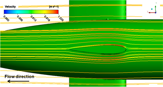
Turbulent flows are common in marine environments. Understanding and predicting turbulence is a critical aspect of hydrodynamic simulations. CFD software employs turbulence models, such as the k-omega SST model, to accurately simulate and analyse turbulent flows.
Transition
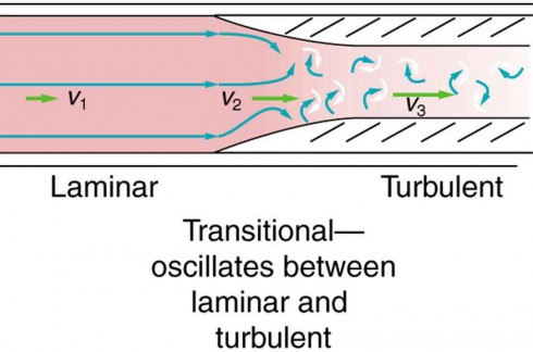
Understanding the different types of fluid flow can be challenging as various factors such as geometry, velocity and boundary conditions can cause laminar, transitional or turbulent flow within a given system. The complexity of fluid dynamics is fundamental and should not be ignored.
Flow transitions can occur in different areas of a fluid system, regardless of the practical scenario. For example, machinery can have a calm and laminar flow at the inlet due to the low velocities and smooth entry conditions. However, the flow inside the machine can become turbulent with increased velocity and complex geometries. Likewise, aerodynamics can have a laminar flow over an airfoil at the leading edge, but turbulent flow can occur downstream.
The transition from laminar to turbulent flow is fundamental research in fluid dynamics. It involves studying Reynolds numbers, boundary layer characteristics and disturbances that trigger the transition. The aim of this field of research is to uncover the underlying mechanisms and predict when and where turbulence will occur.
Turbulent flow is highly complex, characterized by chaotic, three-dimensional eddies and vortices. Predicting the onset of turbulence is a difficult task as it involves transitional states. Due to the complexity of turbulence, it is challenging to include a full description of it in general industrial CFD analysis. Computational limitations and the need for specialized turbulence models make it even more difficult.
In practical CFD analysis, engineers use various turbulence models, such as Reynolds-Averaged Navier-Stokes (RANS) equations or Large Eddy Simulation (LES), to model turbulence. These models approximate turbulent effects based on statistical averaging or filtering. They provide valuable insights into turbulent flows, but they have limitations and may not capture all nuances of real turbulence. Most models aim to capture large-scale structure turbulence or can capture small-scale at the cost of considerable computational resources.
Engineers use simplified turbulence models like RANS, which are computationally efficient and suitable for many engineering applications. Although these models may not capture the detailed physics of the transition from laminar to turbulent flow, they still provide valuable engineering insights.
Boundary Conditions in CFD Analysis
The numerical solution of fluid motion equations necessitates the careful assignment of boundary conditions, which can fall into two categories: Dirichlet conditions, where fixed values are specified, and Neumann conditions, where information about the gradient of the variable is given. These conditions play a crucial role in defining the behaviour of the flow within the computational domain. They are essential for solving various hydrodynamic problems involving ships and other fluid systems.
To illustrate these boundary conditions, let us consider a practical example involving computational physics: calculating the flow field around a ship moving at a constant forward speed. The computational framework is established in a coordinate system moving with the vessel, and the computational domain encompasses a substantial control volume around the ship, where numerical calculations are conducted.
In this scenario:
- For the Dirichlet boundary condition, at the upstream boundary (inlet), where fluid enters the computational domain, the boundary velocity is fixed to match the ship's speed but in the opposite direction. This ensures that, from the ship's perspective, it appears stationary, and the water flows past it. Furthermore, along the ship's surface, the values of fluid velocity components are all set to zero, a condition known as the "no-slip condition."
- For the Neumann boundary condition, symmetry is often assumed, such as a plane along the ship's centerline. This assumption not only simplifies computations but also reduces the size of the computational domain. Additionally, in cases where free surface effects are negligible or not of interest, the water plane can also be considered a symmetry plane, leading to what is known as the "double-body problem." Neumann boundary conditions are applied for the scalar pressure and velocity components tangential to these symmetry planes.
The next section will explore the numerical methods used in Computational Fluid Dynamics to solve fluid flow equations.
Numerical Methods in CFD: Solving Partial Differential Equations
Computational Fluid Dynamics (CFD) software is used to solve the Navier-Stokes equations, which describe the conservation of momentum in fluid flow. These equations, along with other auxiliary equations, are essential for simulating fluid motion. CFD software uses numerical methods to solve these equations, which require significant computational resources such as dedicated hardware. For example, America's Cup teams utilise hundreds or thousands of processors to solve the numerical computations required by CFD software.
Numerical methods discretise the fluid domain into a grid or mesh and approximate the continuous equations at discrete points. Key numerical methods used in Computational Fluid Dynamics include the following:
Finite Difference Method (FDM): FDM approximates derivatives in the equations using finite differences, making it suitable for structured grids
Finite Element Method (FEM): FEM represents the solution as a combination of basis functions and is well-suited for complex geometries and solid mechanics simulations, less so for CFD analysis. At the same time, they are more suitable for stress or modal analysis.
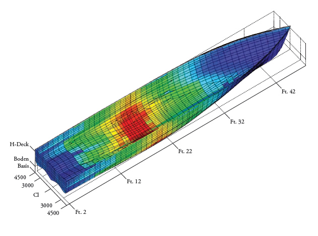
Finite Volume Method (FVM): FVM integrates the equations over control volumes within the grid, making it versatile for irregular geometries and the most popular method overall in CFD analysis.
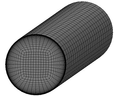
Grid-Based vs Particle-Based Methods
Computational Fluid Dynamics simulations can be categorised into two main approaches: grid-based and particle-based methods.
Grid-Based CFD
In grid-based methods, the fluid domain is divided into a mesh or grid, and equations are solved at discrete grid points. This approach is widely used in CFD software and offers high accuracy for various applications.
The Importance of Meshing in CFD Software
Each type of mesh used in CFD software (tetrahedral, polyhedral, and hexahedral) has advantages and limitations, and the selection should align with the goals and constraints of the simulation. Rather than CFD theory, we talk about CFD software because software vendors often offer integrated packages of meshing and solver.
Tetrahedral Mesh: Pros and Cons
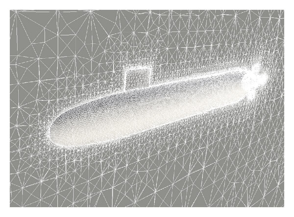
Tetrahedral meshes are highly flexible and can adapt to complex and irregular geometries, making them suitable for vessels with intricate designs. They are relatively easy to generate and require less computational effort for meshing.
Tetrahedral elements may not accurately capture flow patterns around the waterline and hull as other mesh types, particularly in regions where boundary layers or sharp gradients occur. In some cases, tetrahedral meshes might require more cells to achieve comparable accuracy than structured grids.
Polyhedral Mesh: Pros and Cons
Polyhedral meshes balance the flexibility of tetrahedral meshes and the efficiency of hexahedral meshes. They can provide good accuracy for vessel simulations and are especially effective in capturing flow features near the waterline and around hulls.
Polyhedral mesh generation may be more complex than tetrahedral meshing, but it is generally more efficient than hexahedral meshing.
Hexahedral Mesh: Pros and Cons
Hexahedral meshes offer excellent numerical stability and efficiency, making them well-suited for simple or well-defined simulations. They are often used for studying specific areas of interest, such as the flow around specific appendages or components of the vessel.
Hexahedral meshes can be challenging to generate for complex vessel geometries, especially near the waterline and bow regions. Achieving fine boundary layer resolution with hexahedral meshes may require extensive mesh refinement.
Best Practices: Y+
In the context of computational fluid dynamics (CFD) simulations, it is crucial to properly set up the meshing, especially concerning a parameter called "y+" that represents the dimensionless distance from the wall to the first grid point in the fluid domain.
Properly controlling y+ is essential for accurate and reliable CFD results. Here are some key points to consider:
Y+ Range for Wall Functions: The meshing strategy should be designed so that the y+ values at all mesh points adjacent to the wall are greater than 30. Wall functions, commonly used in CFD to model the near-wall behaviour of the fluid flow, are typically valid when y+ is above this threshold. It's generally advisable to keep y+ values below 100 and never let them drop below 11. Some commercial CFD software packages can automatically switch to alternative wall functions if y+ falls below 30. It's essential to check the software's user manual for details on this functionality.
Impact of Mesh Scheme: Different meshing schemes, like cell-centred and cell-vertex schemes, have integration points at different positions within a mesh cell. Consequently, the y+ values associated with wall-adjacent cells may vary depending on the scheme employed in the mesh. Please exercise caution when using different schemes or CFD codes on the same mesh, as this can influence your simulation results!
Friction and Drag Prediction: The values of y+ in cells adjacent to the wall play a critical role in predicting friction and, by extension, drag in the fluid flow.
Correct Wall Function: Verify that the correct form of the wall function is employed to account for wall roughness. Wall functions are used to model the effects of surface roughness on the flow near the wall. Using the appropriate wall function ensures that the simulation considers the roughness of the wall, which can be crucial in specific applications.
Smoothed Particle Hydrodynamics (SPH Methods)
Smoothed particle hydrodynamics is a particle-based method that represents fluid as discrete particles. It is particularly useful for simulating free surface flows and complex interactions but may have limitations in capturing boundary layers and turbulence.
Smooth particle hydrodynamics has been instrumental in studying ship hydrodynamics. Simulating the flow around vessels, especially during complex manoeuvres or in irregular sea conditions, benefits from Smoothed particle hydrodynamics' ability to handle free surface flows easily. Researchers and engineers use Smoothed particle hydrodynamics to investigate ship resistance, propulsion, and the behaviour of ships in waves, aiding in the design and optimisation of ship hulls and propulsion systems.
In the subsequent sections, we will explore CFD software solutions tailored for hydrodynamics and marine engineering applications.

CFD Simulation Software for Hydrodynamics: Key Features of CFD Software
CFD analysis software offers a range of features and capabilities to facilitate hydrodynamic simulations. Some key features to look for in Computational Fluid Dynamics software include:
- User-Friendly Interface: User-friendly interfaces for CFD software make it easier for engineers to set up and run simulations.
- Multiphase Flow Modeling: For applications involving the interaction of two or more fluids, multiphase flow modelling capabilities are essential in CFD software.
- Fluid-Structure Interaction (FSI): FSI enables the simulation of how fluids interact with solid structures, a crucial consideration in marine engineering.
- High-Speed Flow Simulation: Some software packages are optimised for high-speed flow simulations commonly encountered in ship design and underwater propulsion systems.
- Accurate Turbulence Models: The availability of accurate turbulence models, such as the k-omega SST model, enhances the fidelity of simulations performed by CFD software
CFD Software and Simulation Tools - Yacht Simulation
We will examine two complementary methods in vessel simulation, especially yachts. A Velocity Prediction Program (VPP) is a tool used in yacht design to estimate a sailing vessel's performance under various conditions. While VPPs provide valuable insights into boat speed and sail trim, they can be complemented and validated with Computational Fluid Dynamics simulations, which offer a more detailed analysis of fluid flow around specific components of the boat. These tools help yacht designers optimise vessel performance and make informed design decisions.
Stage 1: the VPP "Workhorse"
A Velocity Prediction Program (VPP) is a computational tool used in naval architecture and yacht design to predict the performance of a sailing vessel under various conditions. VPPs are particularly common in designing and optimising racing yachts, but they can also be used for other types of sailing vessels. The primary purpose of a VPP is to estimate the boat's speed and performance characteristics for different combinations of wind speed, wind angle, and sail settings.
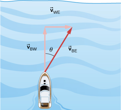
Here's how a VPP typically works. A VPP consists of two main components: hydrodynamic and aerodynamic models. These models describe how a boat interacts with water (hydrodynamics) and wind (aerodynamics). The hydrodynamic model calculates the boat's resistance through the water, while the aerodynamic model calculates the forces and moments generated by the sails in the wind.
The user inputs environmental conditions such as wind speed, wind direction, sea state, and sometimes current data into the VPP. These conditions can be real or hypothetical scenarios that the boat might encounter during a race or voyage.
The VPP also requires information about the boat's geometry, including hull shape, sail plan, mast height, keel shape, and rudder design. This data is essential for the hydrodynamic and aerodynamic calculations. Using the input data, the VPP calculates the boat's performance. It estimates variables like boat speed, heel angle (tilt of the boat), and sail trim for each combination of environmental conditions and sail settings. The goal is to find the optimal configuration that maximises boat speed for a given scenario.
Stage 2: Refinement Analysis with CFD Software
While a VPP provides valuable performance predictions, it somewhat simplifies the fluid dynamics calculations. CFD simulation software, on the other hand, is a more detailed and sophisticated numerical approach to simulate the flow of fluids (air or water) around objects, including sails, hulls, and appendages.
VPP and CFD software are often used together in yacht design. CFD software can provide more detailed insights into the fluid flow around specific components of the boat, helping designers refine sail shapes, optimize hull design, or improve keel and rudder configurations. CFD software allows for a finer level of detail but is computationally intensive and typically requires specialized software and expertise.
Stage 3: More Information on Different Types of CFD Analysis Density
These are the primary CFD analyses conducted for vessels:
(1) Static resistance studies. In this analysis, the vessel is submerged in water, and only the submerged portion is considered. This study helps evaluate the vessel's hydrodynamic performance, particularly its resistance to forward motion.
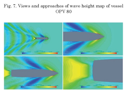
(2) Sink and trim analysis. This analysis simulates the vessel in a virtual towing tank. It provides valuable data on the vessel's vertical sink (z) and angular trim (an angle) under various velocity conditions. Additionally, it examines the wave pattern formed by the vessel, which is crucial for understanding its interaction with the surrounding water. Understanding the wave pattern helps assess how efficiently the vessel moves through the water. An inefficient wave pattern can indicate excessive energy loss, impacting the vessel's fuel consumption and overall performance.
(3) Seakeeping analysis. Within this framework, the focus extends to assessing the vessel's performance in challenging sea conditions. This includes evaluating its response to wave patterns, wind forces, and sea states. One interesting aspect considered in seakeeping analysis is the phenomenon known as 'green water.' Green water refers to waves that break over the deck of a vessel, potentially causing damage and posing safety risks. The seakeeping analysis assesses the vessel's ability to withstand and minimise green water events, ensuring the safety and functionality of the vessel in harsh maritime environments. Key factors such as motion characteristics, accelerations, wave-induced loads, and the prevention of green water ingress are thoroughly examined to optimise the vessel's design and operational capabilities.
The above is the "menu" for typical vessels.
When dealing with sailboats, aerodynamics and the sails' interaction with the wind are important in CFD analyses, reflecting the vessel's primary mode of propulsion.
However, aspects of hydrodynamics and seakeeping are still relevant, albeit to a lesser extent, for overall vessel performance and safety.
What Vessels? Famous Datasets
If you are new to the sector, you could wonder how long it would take to get hold of marine vessel shapes, maybe to generate your dataset. We have some good news for you. Several publicly available benchmark series in marine CFD provide standardised hull shapes and scenarios for researchers and engineers to test and validate their CFD simulations. These benchmark series are valuable resources for the marine engineering community to assess the accuracy and reliability of their numerical models. Here are a few notable benchmark series:
The Wigley Hull Series: The Wigley hull series consists of standardised hull forms ranging from slender to full-figured shapes. These hulls are commonly used for resistance and propulsion simulations. They serve as a benchmark for assessing the performance predictions of CFD codes and comparing results across different research groups.
The DTMB 5415 Series: The David Taylor Model Basin (DTMB) 5415 series includes various hull forms, each designated with a different appendage configuration (e.g., single-screw, twin-screw, or twin-skeg). These benchmarks are widely used for studying different hull types' resistance, propulsion, and seakeeping characteristics.
The MARINTEK Ships: The Norwegian Marine Technology Research Institute (MARINTEK) has released a series of benchmark cases involving various ship types, including containerships, Ro-Ro vessels, and offshore structures. These benchmarks cover a wide range of applications in the maritime industry.
Marine Applications of Computational Fluid Dynamics
Computational Fluid Dynamics has a wide range of applications in marine engineering, where it aids in the design, analysis, and optimisation of various marine systems and structures.
One of the primary applications of Computational Fluid Dynamics in marine engineering is ship design. Hydrodynamic simulations enable engineers to assess the performance of different hull shapes, propeller designs, and rudder configurations. By running simulations under various operating conditions, such as varying speeds and sea states, designers can optimise ships for fuel efficiency, stability, and seaworthiness.
Submarines, autonomous underwater vehicles (AUVs), and remotely operated vehicles (ROVs) benefit from CFD simulations to assess manoeuvrability, drag, and control in underwater environments.
Computational Fluid Dynamics helps evaluate the stability of offshore platforms and their resistance to waves and currents. It also aids in the design of risers and mooring systems.
Optimising propulsion systems, including propellers and thrusters, is essential for achieving high efficiency and manoeuvrability in marine vessels. Computational Fluid Dynamics assists in designing and analysing these systems.
Multiphase Flows and Fluid-Structure Interaction
Many marine engineering scenarios involve multiphase flows, where two or more fluids with distinct properties interact. For example, the interaction of air and water in wave breaking or the behaviour of oil and gas in offshore drilling operations. CFD analysis software enables engineers to model these complex interactions accurately.
Fluid-structure interaction simulations are vital when considering how water loads affect the structural integrity of marine systems. Understanding FSI is crucial for designing robust offshore platforms, ship hulls, and underwater equipment.
The following section will explore advanced techniques and models used in hydrodynamic simulations.
Advanced Techniques and Models
Turbomachinery Applications
Turbomachinery, including pumps, turbines, and compressors, is prevalent in marine engineering. CFD is extensively used to optimise the design of these machines for efficiency and performance.
Modeling Complex Chemically Reacting Systems
It is essential to model complex chemically reacting systems in some marine scenarios, such as combustion engines or chemical reactions in water. CFD analysis software can simulate the interactions between chemical species and combustion processes.
Simulating Smoke Propagation in Marine Environments
Smoke and fire safety are critical concerns in marine engineering. Computational Fluid Dynamics simulations can predict how smoke propagates within enclosed spaces on ships, helping design effective ventilation and fire safety systems.
Modelling Gas Accretion in Underwater Structures
Understanding gas accretion is crucial for underwater structures like pipelines and subsea equipment. CFD software can model the behaviour of gas bubbles in water and their impact on system performance and safety.
In the upcoming section, we will address challenges and considerations in hydrodynamic simulations.
Challenges and Considerations in Marine Applications of Computational Fluid Dynamics
Dealing with High-Speed Flows. High-speed flows, often encountered in ship propulsion, present turbulence, and pressure variations challenges. Specialised CFD analysis software and high-performance computing are necessary to accurately simulate and analyse these flows.
Addressing High Costs and Resource Demands. While CFD analysis software offers cost savings compared to physical experiments, it still requires significant computational resources. High-resolution simulations and large-scale models demand powerful computing infrastructure, which can be costly to set up and maintain.
Achieving High Accuracy in CFD Simulations. Accuracy is paramount in hydrodynamic simulations. Choosing appropriate turbulence models, grid resolution, and boundary conditions is crucial to achieving reliable results.
Managing Large-Scale Structures in CFD Analysis Software. In marine engineering, simulations often involve large structures like ships or offshore platforms. Managing the computational complexity of such models requires careful consideration of meshing techniques and parallel computing strategies.
The following section will explore best practices for optimising CFD simulations in hydrodynamics.
Understanding Multiphase Flow: VOF
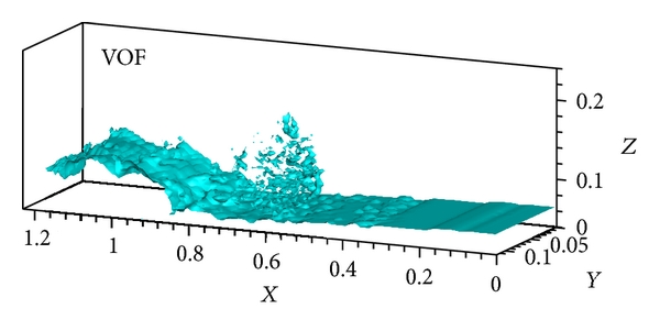
The Volume of Fluid (VOF) method is a computational technique used in CFD software to simulate situations where two distinct fluid phases are present, such as air and water. In this method, both phases are treated as a single continuous fluid with their positions defined by assigning a volume fraction of 0 or 1, indicating whether a given point in the computational domain is occupied by one phase or the other.
The key points about the VOF method are as follows:
Description of Phases: The VOF method represents both fluid phases as a single, continuous fluid. The positions of these phases are determined by assigning a volume fraction of either 0 or 1, where 0 represents one phase (e.g., air), and 1 stands for the other phase (e.g., water).
Free Surface Identification: The free surface, which separates the two phases, is identified by locating the region with a rapid change in the volume fraction.
Transport Equation: An additional transport equation is solved to track the volume fraction of one of the phases. This equation generally takes a similar form to the mass transport equation, allowing the volume fraction to evolve as the simulation progresses.
Solution Algorithm: The VOF method often employs algorithms like the SIMPLE (Semi-Implicit Method for Pressure-Linked Equations) method to solve for variables like pressure, velocity components, volume fraction, turbulent kinetic energy, energy dissipation rate, and eddy viscosity. The process involves iteratively correcting velocity components using a pressure-correction equation.
Iterative Process: The equations governing the fluid behaviour, including volume fraction, are solved iteratively until a predefined tolerance level is achieved, ensuring the accuracy of the simulation results.
Interface Sharpening: To enhance the interface representation between the two phases, interface sharpening algorithms are employed. These algorithms refine grid cells with volume fraction values between 0 and 1, improving the accuracy of the free surface representation.
A Nasty Artifact
Numerical ventilation in VOF-based CFD simulations refers to the emergence of spurious or unphysical voids or bubbles in the fluid domain, typically along solid surfaces, such as a keel in a marine application. This artifact occurs due to numerical inaccuracies or limitations in the simulation method, particularly in scenarios with rapid changes in fluid properties, like air-water interfaces. Numerical ventilation can lead to erroneous predictions of flow and pressure distributions, and it often necessitates advanced modelling techniques or mesh refinement to mitigate these spurious effects and achieve more accurate results in marine hydrodynamics simulations. Ignoring the artifact's existence can lead to dangerous overoptimistic appraisals of the hydrodynamic performance of your vessel!
Understanding Rotating Bodies for Marine Applications
Incorporating rotating conditions is crucial when simulating systems involving rotational components, such as ship propellers. These conditions represent the interplay between the fluid and these rotating elements. Two fundamental approaches in this context are Multiple Reference Frames (MRF) and Rigid Body Motion, and occasionally, the use of an actuating disk simplification may be appropriate.
Multiple Reference Frames (MRF)
The Multiple Reference Frames approach is a powerful tool for rotating machinery simulations. This method makes an important assumption known as symmetry. Under this assumption, the fluid domain is divided into multiple zones, each with its reference frame. The critical idea here is that these reference frames allow different parts of the simulation domain to rotate independently, reflecting the actual behaviour of the simulated components.
- Advantages: MRF simplifies the simulation by decoupling the fluid flow in stationary and rotating zones, significantly reducing computational costs. It is particularly effective when the rotational speed is uniform throughout the domain.
- Applications: MRF is commonly employed when simulating scenarios where the fluid interacts with rotating components reasonably uniformly, such as in ship propulsion or centrifugal pumps.
Rigid Body Motion with Sliding Interface
In more intricate configurations, where the rotational behaviour of the components is not uniform, the rigid body motion approach with a sliding interface between static and rotating parts becomes essential. This method provides a more detailed representation of how each part moves and interacts with the fluid.
- Advantages: Rigid body motion offers greater flexibility and accuracy when modelling non-uniform rotation or complex interactions between a system's rotating and stationary parts.
- Applications: This approach is often applied to scenarios where the rotating machinery exhibits non-uniform rotational behaviour or complex geometry, as seen in certain mixers or industrial agitators.
Actuating Disk Simulation
When a simplified representation is acceptable, a propeller or similar rotating component can sometimes be approximated as an actuating disk. This simplification streamlines the simulation by representing the entire rotating component as a single entity.
- Advantages: The actuating disk approach is highly computationally efficient and suitable when a detailed representation of the individual blades or components is unnecessary.
- Applications: This simplification is utilised when the fine details of the rotating machinery's behaviour are not critical to the simulation's objectives or when computational efficiency is paramount.
Conclusion - Optimizing CFD Simulations for Marine Applications
At the closure of this article, let us remind that to obtain accurate results in hydrodynamic simulations, engineers should consider the following best practices:
- Validate simulation results against experimental data when possible.
- Use high-quality meshing techniques to ensure grid independence.
- Carefully select turbulence models based on the specific flow conditions.
- Conduct sensitivity analyses to understand the impact of model parameters.
- Employ adaptive mesh refinement for resolving critical flow features.


