Electric Motor Simulation: Powerful Tool for Design Optimization

An electric motor is a device converting electrical into mechanical energy, providing motion to various electric machines.
Electric motors have become indispensable in the automotive industry for powering electric vehicles and in aerospace. Electric motors help harness power from wind turbines and hydroelectric generators in renewable energies.
In this article, we will review design requirements for electric motor design and explore finite element analysis and deep learning in electric motor design. We will start with the influence of electric motors in electric vehicles, review some physics, and introduce the simulation process.
We will finally hint at new solutions with deep learning applications. With accelerated design space exploration via deep learning software, electric motors can hit the market faster, with lower costs and enhanced motor's performance.
Electric Vehicles and Electric Motors
Electric motors play a fundamental role in powering electric vehicles. They are the primary propulsion system, driving the wheels and enabling motion without relying on internal combustion engines. The power output of an electric motor affects the vehicle's acceleration, top speed and performance. A motor with higher power can deliver greater torque and acceleration, resulting in improved vehicle performance such as faster acceleration time and higher top speed.
The energy efficiency of an electric motor determines how effectively it converts electrical into mechanical energy. More efficient motors result in reduced energy losses, extending the vehicle range and improving fuel efficiency in hybrid vehicles.

Basic Principles of Electric Motors
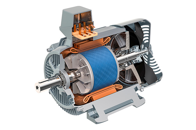
An electric motor is an electric machine convertinbg electrical into mechanical energy or the other way around, through the principle of electromagnetic induction.
Stator-Rotor Interaction
Within the motor, some magnets or electromagnets generate magnetic fields. When an electric current "I" flows through coils of wire in the motor, it creates an (electro)magnetic field with strength "B" around it, whose polarity depends on the direction of the current. These fields interact, typically between the motor's stationary part (the stator) and the motor's moving part (the rotor).
The stator-rotor interaction generates a force called electromagnetic torque τ_em, which causes the rotor to rotate. This rotational motion is used to perform mechanical work, such as driving machinery or propelling vehicles. Quantitatively we express it as τ_em = B I A * sin(θ) where "A" is the cross-sectional area of the coil through which the electric current flows and "θ", the angle between the magnetic field and the direction of current flow.
What Is Electric Motor Simulation?
In an optimized iterative design process, at least three types of physical properties and corresponding types of simulation can be investigated for the simulation of electric motors to support electric motor design.
Electromagnetic Simulation
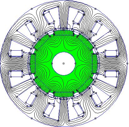
An accurate electromagnetic simulation is needed for the motor design to analyze magnetic fields, flux distribution, and torque generation. This enables engineers to optimize motor performance and efficiency while minimizing losses.
Thermal Analysis
Once the electromagnetic design phase is completed, we focus on the electric motor's critical aspect of cooling. The efficiency and longevity of the motor rely on accurate effective thermal management. Thermal simulation is an indispensable tool in this stage, offering insights into heat dissipation and temperature distribution.
With thermal simulation techniques, we can evaluate the thermal performance of the electric motor under various operating conditions. This analysis provides information on how long the motor can sustain its maximum power output without overheating.
Thermal design typically involves Finite Element Method (FEM) simulations. FEM analyses simulate heat flow within the motor components, allowing engineers to visualize temperature gradients and identify potential hotspots before failures occur.
Design adjustments become imperative when the simulation indicates that the electric motor exceeds safe temperature thresholds. This could involve revisiting the motor design to enhance heat dissipation properties or optimizing the cooling system. Failure to address excessive heat buildup can compromise motor performance, energy efficiency, and operational lifespan.
Integrating thermal simulation into the design process enables engineers to make informed decisions, ensuring that the electric motor operates reliably and efficiently.
Mechanical Analysis
Mechanical simulation includes the simulation of mechanical vibrations, which can adversely affect motor performance and lead to unwanted noise and vibration. This is also called the acoustic simulation of electric motors and drives. Harshness analysis identifies noise and vibration sources, allowing engineers to design quieter, smoother-running motors.
Multiphysics simulation addresses the issue of having separate disconnected simulations and separate software. With this approach, engineers can analyze and simulate the interactions between electromagnetic, thermal, and mechanical phenomena within the motor, understanding its behavior and enabling accurate design optimization.
Software Simulation Process
Simulating an electric motor with CAD-CAE software includes three phases: preprocessing, processing, and postprocessing.

Preprocessing Phase with CAD & CAE Software
In CAD software, a digital model of the electric motor geometry is created by designer. In mesh generation, this geometry is imported in a specific CAE software tool and is divided into smaller elements to facilitate numerical analysis. Engineers assign appropriate material properties to different motor components during the material properties phase. Properties dictate how materials interact with electromagnetic fields. Material properties include magnetic permeability, electrical conductivity, and thermal conductivity. Finally, engineers specify operating conditions and loads applied to the motor.
Processing Phase with CAE Software
This phase is the solver setup and simulation: engineers set up the simulation parameters and run the simulation using specialized software tools and often cloud computing or specialized hardware.
Post Processing with CAE Software
Finally, engineers analyze the simulation results, which may include temperature distribution, magnetic flux density, torque output, and mechanical stresses.
An Example of Electric Motor Design: BLDC
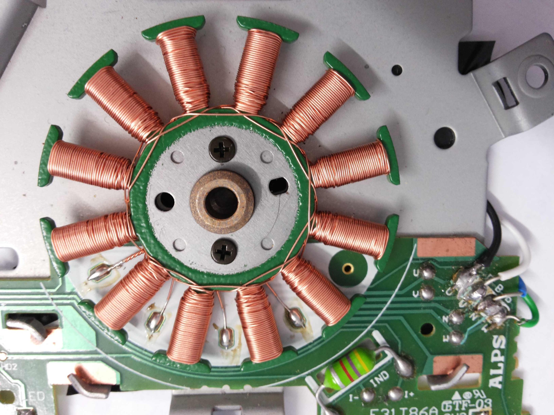
BLDC motors, short for Brushless DC, are a type of electric motor commonly used in various applications due to their efficiency and reliability. BLDC's maintain a constant speed and torque output in steady state operation without any fluctuations. Unlike traditional brushed DC's, BLDC's do not use brushes for commutation, leading to reduced maintenance and longer lifespan. BLDCs rely on electronic controllers to precisely control the motor's operation by switching the current flow through the motor windings.
This design eliminates the risk of sparking and reduces electromagnetic interference, making BLDC motors ideal for a range of applications requiring high precision and stability. In EVs, where they are used as the propulsion system to drive the wheels.

Latest Simulation Development: Deep Learning to Predict Electric Motor Design Performance
By harnessing the power of Deep Learning, surrogate models can significantly outpace traditional Computer-Aided Engineering (CAE) methods in terms of speed. This breakthrough allows for much quicker iteration cycles, cutting down on the time and resources needed to develop electric motors solutions for market release.
So, how exactly is a surrogate model crafted? It starts by feeding datasets containing information from Computer-Aided Design (CAD) and Finite Element Analysis (FEA) simulations into a Deep Learning system.
In this exciting development of analysis capabilities, Deep Learning, by using specialized neural networks, learns from these datasets to create a predictive model. This model links predictions with changes in shapes or designs. This helps predict how changes in the design affect the performance of the electric motor, making the design process much more efficient and streamlined.
As a result, products can hit the market with enhanced quality, reduced costs, and better performance - and hit it faster!


