Conjugate Heat Transfer: Basics, Best Practices & Applications
Heat transfer is the phenomenon of energy exchange due to temperature differences, and conjugate heat transfer (CHT) is the combined heat exchange between a solid and adjacent fluid(s), uniting conduction in solids with convection in fluids in one coupled system. Heat transfer is seldom confined to a single material or medium; real-world systems involve continuous interactions between solids and fluids, and CHT captures these dynamics.
Key takeaways
Quick facts:
Conjugate heat transfer solves conduction in the solid and convection in the fluid together, so the two temperature fields determine each other.
The conjugate approach replaces the assumed convective heat transfer coefficient of classical thermal analysis with a computed local value.
The method sets the design limits for electronics cooling, brakes, heat exchangers, and turbine blades, wherever component temperature determines service life.
Physics-aware AI trained on solver results returns thermal field predictions in near real time.
For engineers, scientists, and simulation professionals working on thermal analysis and design optimization, this framework is used to evaluate how heat actually moves in applications such as electronics cooling, automotive braking systems, aerospace structures, heat exchangers, and energy systems. In this article, we break down the fundamentals, physics, and mathematics of heat exchange across multiple media, then move on to simulation setup and best practices, numerical methods, engineering applications, and how machine learning in CFD can enhance CHT analysis.
Table of contents
What is conjugate heat transfer?
How does conjugate heat transfer work?
Simulation setup and best practices for CHT
Transient heat transfer
Transient conduction equations
Solid-flow interface
Mathematics of conjugate heat transfer: looking for analytical solutions
Numerical methods: solving complex equations
AI and CAE simulation
Engineering applications of conjugate heat transfer
Examples of conjugate heat transfer in industrial processes
Conclusions on CHT
FAQ
Sources
What is conjugate heat transfer?
Conjugate Heat Transfer, or CHT, is the concurrent heat energy exchange between a solid and adjacent fluid(s). It integrates conductive heat transfer in the solid and convective heat transfer in the fluid. A key aspect of CHT analysis is the continuity of heat flux at the interface, which represents thermal interactions between media.
CHT models how heat flows by solving the heat conduction and fluid flow equations simultaneously for greater accuracy in complex engineering systems. For instance, CHT can be encountered in various types of heat exchangers.
Traditional thermal analysis often relies on a constant convective heat transfer coefficient applied over the whole wetted surface. That assumption can be inaccurate because the local coefficient varies along the wall with boundary-layer growth and flow separation.
CHT eliminates the need for assumed convective heat transfer coefficients at surfaces. The solver computes the local wall heat flux directly from the resolved fluid and solid temperature fields, so the coefficient is a result of the calculation rather than an input.
What is heat exchange, and why does it occur (macroscopic explanation)
Energy transfer as heat occurs whenever two regions at different temperatures are placed in thermal contact. The second law of thermodynamics fixes the direction of that transfer: within an isolated system, energy passes from the region at higher absolute temperature to the region at lower absolute temperature, and the total entropy increases. Conduction, convection, and radiation are the three mechanisms carrying the transfer. The outcome is that systems move toward thermal equilibrium.
Let us start with a crude representation of two “cells” or blocks forming an isolated system. Cell 1 has absolute temperature T₁, and cell 2 has absolute temperature T₂, with T₁ greater than T₂. No temperature profiles develop within the cells or blocks, an idealization valid when the Biot number is small enough that internal conduction resistance is negligible compared with surface resistance. This initial situation has a lower entropy S.
There is a difference
ΔT = T₁ − T₂,
and the natural tendency is for
ΔT → 0,
leading to thermal equilibrium.
Transferring an increment of energy δQ from cell 1 to cell 2 changes the total entropy of the isolated system by
dS = δQ (1/T₂ − 1/T₁) = δQ (T₁ − T₂) / (T₁ T₂)
The expression remains positive while T₁ exceeds T₂. Transfer in the opposite direction would reduce the total entropy and is therefore excluded. As energy flows as heat, entropy increases to a new value S' > S, reaching a maximum at equilibrium. The common final temperature follows from energy conservation and lies between T₂ and T₁, weighted by the heat capacities of the two blocks.
What are the CHT outputs?
Coupling conduction and convection, CHT is a tool for predicting the spatial distribution of temperature, heat transfer rates, and critical thermal parameters. These parameters are essential for optimizing designs in the automotive, aerospace, civil engineering, electronics cooling, and energy industries.
Do not neglect radiation
In many cases, radiation heat transfer is also essential. This is particularly true at high temperatures because radiation transfers energy through electromagnetic waves and does not require a physical medium. So, while CHT focuses on conduction and forced and natural convection, advanced simulations can incorporate thermal radiation. Radiation must be considered in industrial furnaces, spacecraft thermal design, and high-temperature reactors to avoid significant errors in heat transfer predictions.
Naive example
A domestic convection oven is a simple example of fully combined heat transfer. Forced convection (via a fan) and natural convection (via buoyancy) circulate air; conduction transfers heat through metal surfaces and food, while radiation from the oven walls and heating elements directly heats the meal.

This illustrates how radiation interacts with conduction and convection. Common gases, such as air, are effectively transparent to thermal radiation, whereas most solids are opaque, resulting in surface-to-surface radiation within cavities. However, carbon dioxide and water vapor are semi-transparent in specific spectral bands, allowing radiation to be absorbed, emitted, and scattered within the medium.
Radiation is often negligible at low temperatures and becomes dominant at high absolute temperatures. Conduction and convection are proportional to ΔT, i.e., they are linearly proportional to the temperature difference. Net radiative exchange between two surfaces follows a nonlinear relationship, scaling with the difference of the fourth powers of the absolute temperatures, so its share of the total heat transfer increases rapidly as the temperature level rises.

How does conjugate heat transfer work?
Conjugate heat transfer refers to the combined interactions between fluids and solids. Conduction, forced and natural convection, and occasionally radiation coexist. While fluids transfer heat by forced and natural convection, solids conduct heat. Many situations need a unified approach to thermal analyses. Below, we investigate the fundamental modes of heat transfer. Later, we will show typical heat exchanger design software from CFD to deep learning.
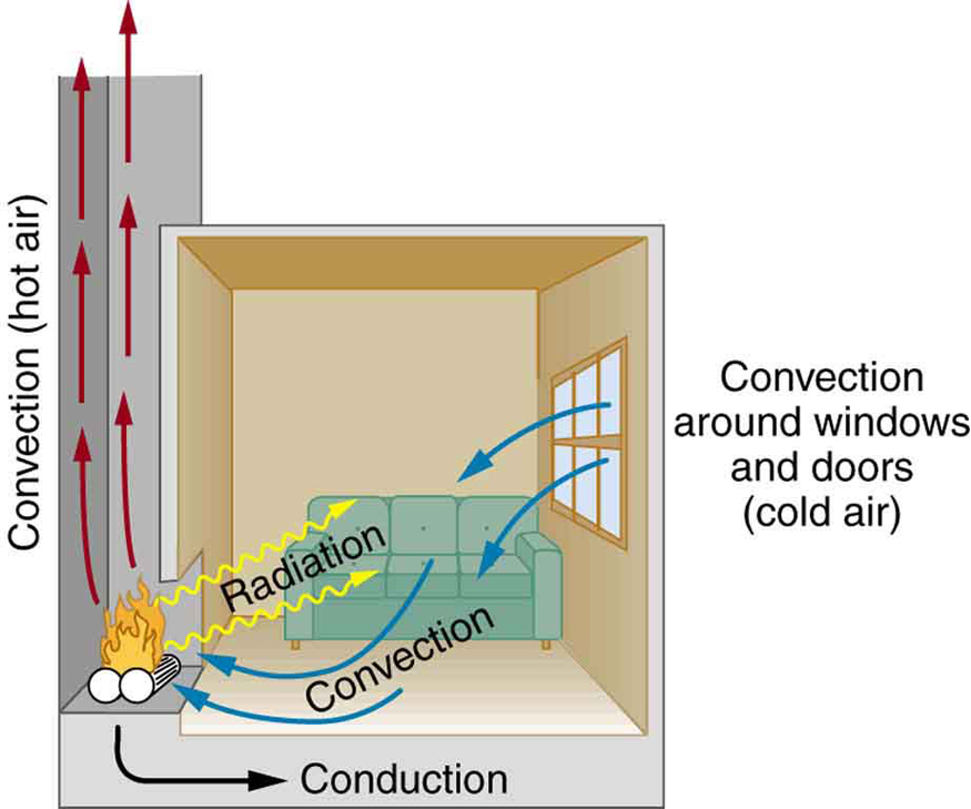
Heat transfer process in fluids
Heat transfer occurs through conduction and convection in fluids, with convection often dominating due to fluid motion. The fluid usually serves as an energy carrier over long distances. Buoyancy forces drive natural convection, while forced convection is typically fluid flow induced by external forces, such as fans for airflow and pumps for liquid coolant flow. Convection allows fluids to distribute heat more than conduction alone. Forced convection is the most common way to achieve a high heat transfer rate in thermal management applications.
Depending on the flow conditions, water in forced convection can exhibit convective heat transfer coefficients typically ranging from 50 to 10,000 W/(m²·K).
Reference: Engineering ToolBox, "Understanding Convective Heat Transfer: Coefficients, Formulas & Examples," accessed August 20, 2026
Pure conduction in a liquid such as water is far weaker. The thermal conductivity of water at 20 °C equals about 0.6 W/(m·K), so a stagnant 5 mm layer offers an equivalent coefficient near 120 W/(m²·K), and a stagnant 50 mm layer near 12 W/(m²·K).
Reference: Engineering ToolBox, "Thermal Conductivity of Water: Temperature and Pressure Data," accessed August 20, 2026
The following equation (Newton's law of cooling) quantifies convective heat transfer:
Q = h A ΔT
Q = heat transfer rate,
h = convective heat transfer coefficient,
A = heat transfer surface area, and
ΔT = the difference in temperature between the fluid and surface.
The temperature difference (ΔT) between the fluid and the surface is a driving force behind convection.
Ultimately, the convective heat transfer rate depends on ΔT, A, and the complex interactions that govern the convective heat transfer coefficient h (fluid velocity, turbulence intensity, and surface conditions), which determine how effectively heat moves within a fluid system.
The convective heat transfer coefficient h encapsulates multiple physical effects, including fluid motion, boundary layer behavior, and turbulence. As fluid flows over a surface, it forms a boundary layer. The boundary layer is a thin region where velocity and temperature gradients develop. The nature of this layer (laminar or turbulent) significantly influences heat transfer. With intense mixing and enhanced interaction, turbulent flow significantly increases h, leading to greater heat exchange.
Heat transfer process in solids
Heat conduction in solids transfers thermal energy from hot to cool areas. Steel and mineral wool differ in thermal conductivity by about three orders of magnitude, and common brick falls between them. Fourier's Law describes heat flux in solids as proportional to the temperature gradient (∇T). Heat flux is proportional to the temperature gradient and the material's thermal conductivity.
Reference: Engineering ToolBox, "Thermal Conductivity of Common Materials - Solids, Liquids and Gases," accessed August 20, 2026
This law aids engineers and scientists in designing thermal systems. Heat conduction describes the transmission of thermal energy in metals and insulators.
Research by pioneers such as Joseph Fourier advanced our understanding of heat transfer. Jean-Baptiste Biot's early 19th-century experiments measured heat flow through materials, laying the groundwork for the study of thermal conductivity. Fourier's Law links heat flux, temperature gradient, and thermal conductivity.

Thermal conductivity
Thermal conductivity is a material property that quantifies a substance's ability to conduct heat. It is measured in Watts per meter-kelvin (W/(m·K).
The thermal conductivity of solids varies with the material. Metals such as copper and aluminum exhibit high values, while insulating materials such as wood and foam have much lower values.
Thermal conductivity is often associated with solids, but that association is a misconception. Gases and liquids also conduct heat, and their conductivity is often underestimated because convective heat transfer dominates whenever the fluid moves. Effective heat transfer capability in a fluid therefore combines thermal conductivity with the influence of fluid motion, which enhances heat distribution. Thus, while fluids may have lower thermal conductivity values than solids, their ability to transfer heat through convection can be considerable.
Fundamental differences: conductive and convective heat transfer
The linearity of conduction and convection stems from their governing equations (Fourier's law and Newton's law of cooling), which describe how heat transfer varies linearly with temperature differences. However, the underlying physics is different!
Conduction relies on the transfer of energy through molecular interactions within materials. The linear relationship arises because the heat transfer rate is proportional to temperature differences and is fundamentally linked to the material property, i.e., thermal conductivity κ. Thermal conductivity is a measurable material property that indicates how well a substance conducts heat at a given temperature.
Convection concerns the bulk movement of fluid and the energy transfer resulting from this motion. The linear relationship in convection assumes that the heat transfer rate is directly proportional to the temperature difference between the surface and the fluid. Warmer fluid rises while cooler fluid sinks because buoyancy depends on density changes tied to the thermal expansion coefficient, creating convective currents. The convective heat transfer coefficient (h) is a measurable property that characterizes the effectiveness of convective heat transfer in a fluid. It incorporates factors related to fluid motion, flow dynamics, and fluid properties, making it considerably more complex than the thermal conductivity of solids.

For the eager, simulation-conscious readers, let us anticipate that modeling conduction numerically can be handled effectively without CFD, whereas simulating convection requires it and becomes significantly more complex and challenging, especially in natural convection.
Interaction between solids and fluids
When solids and fluids interact thermally, heat transfer occurs at their interface, combining conduction within the solid and convection in the fluid. This interplay appears in heat exchangers, cooling systems, and thermal insulation applications. The solid conducts heat internally at the interface, while the fluid transports it away via convection.
Modeling CHT requires solving coupled heat-transfer equations in both domains, with a single interface temperature at the boundary. At the solid-fluid interface, temperature and heat flux must be continuous across both domains, linking the solid surface temperature to the fluid temperature field. This ensures accurate predictions of temperature distribution and thermal performance in complex systems.
The efficiency of this process depends on:
Thermal conductivity (κ) of the solid – High-conductivity materials, such as metals, facilitate rapid heat distribution, while insulators, such as ceramics, slow it down
Convective heat transfer coefficient (h) of the fluid – Higher values indicate enhanced heat exchange, influenced by fluid velocity, turbulence, and properties
Contact surface area (A) and temperature difference (ΔT) – Heat transfer is driven by larger interfaces and greater temperature differences
Steady-state and transient, heat sinks and heat sources
A typical CHT scenario involves a heated solid surface in contact with a cooling fluid. Heat spreads within the solid via conduction, reaching the interface where it is transferred to the fluid. Flow characteristics, such as turbulence and boundary-layer development, in forced convection significantly affect heat dissipation.
The phenomenon can be transient, in which the system starts in a non-equilibrium state and evolves toward equilibrium, or steady, in which continuous heat input and removal create a stable temperature distribution. For example, if a heat source is on the solid side, CHT helps determine how to optimally conduct heat to the heat sink, often aided by devices such as fans or pumps. Solid heat sinks are usually made of metal with high thermal conductivity, such as copper or aluminum.
Example of conjugate heat transfer in action
A clear example of conjugate heat transfer at work is the thermal response of a house with stone walls during summer. Sun-heated walls absorb heat at the outer surface, and the low thermal diffusivity of stone, near 1.15 × 10⁻⁶ m²/s for sandstone, slows the passage of that heat indoors. The daily thermal wave penetrates a characteristic depth √(2α/ω) of approximately 0.18 m, so a wall half a meter thick reduces the indoor swing to roughly 6 percent of the outdoor swing and shifts its peak by around eleven hours. This "buffering effect" helps keep the interior cooler. The stone gradually releases stored heat at night, stabilizing indoor temperatures and preventing fluctuations. The stone's greater thermal inertia ensures stable interior temperatures despite changes outside.
Reference: Engineers Edge, "Thermal Diffusivity Table," accessed August 20, 2026

Governing equations for conjugate heat transfer
When analyzing conjugate heat transfer, the objective is to simultaneously solve the heat conduction equation in solids and the conjugate convective heat transfer equation in fluids.
The governing equation for heat conduction is the Fourier unsteady-state equation:
∇·(κ∇T) = ρc ∂T/∂t
where material properties are
κ = the thermal conductivity of the solid material,
ρ = the material density, and
c = the specific heat capacity,
we want to solve for temperature T=T(x, y, z; t), i.e., a temperature distribution over space with a spatial gradient ∇T and over time with a time derivative ∂T/∂t.
The boundary conditions for solid and fluid domains must be appropriately defined to ensure a consistent and accurate analysis.
Numerical methods for 3D heat transfer simulations
Solving conjugate heat transfer problems in three dimensions requires numerical methods to handle coupled conduction and convection equations. Analytical solutions are often impractical for complex geometries. Computational approaches such as the Finite Volume Method (FVM), Finite Element Method (FEM), and Finite Difference Method (FDM) are standard.
1. FVM is most commonly used in CFD. It discretizes governing equations over control volumes, ensuring energy conservation across each cell. Thus, the Finite Volume Method is well-suited to fluid flow and convection-dominated problems.
2. FEM divides the domain into elements and applies weighted residual techniques to approximate temperature fields, offering flexibility for complex geometries and anisotropic materials.
3. The Finite Difference Method (FDM) uses Taylor series approximations to replace differential equations with algebraic equations on a structured grid. While simple, it is less adaptable to irregular geometries than FVM and FEM; therefore, commercial codes for engineers rely more heavily on FVM and FEM.
Simulation setup and best practices for CHT
Accurate simulations in conjugate heat transfer require a systematic approach that follows precise guidelines. By following these practices, engineers can effectively use this analytical method to gain insights into heat transfer interactions in solid and fluid domains.
Geometry preparation
A well-prepared geometry is crucial for accurate CHT simulations. Ensure all solid-fluid interfaces are clearly defined, and remove unnecessary geometric details that would increase computational cost without improving accuracy. Avoid sharp edges or thin walls that could cause meshing issues and numerical instabilities.
Mesh quality and best practices in meshing
Mesh generation forms the basis of any simulation. In conjugate heat transfer, a well-structured mesh is crucial for capturing the geometry and resolving temperature and velocity gradients. A balanced mesh must be sufficiently detailed to represent complex features without incurring high computational costs.
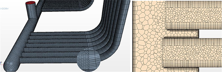
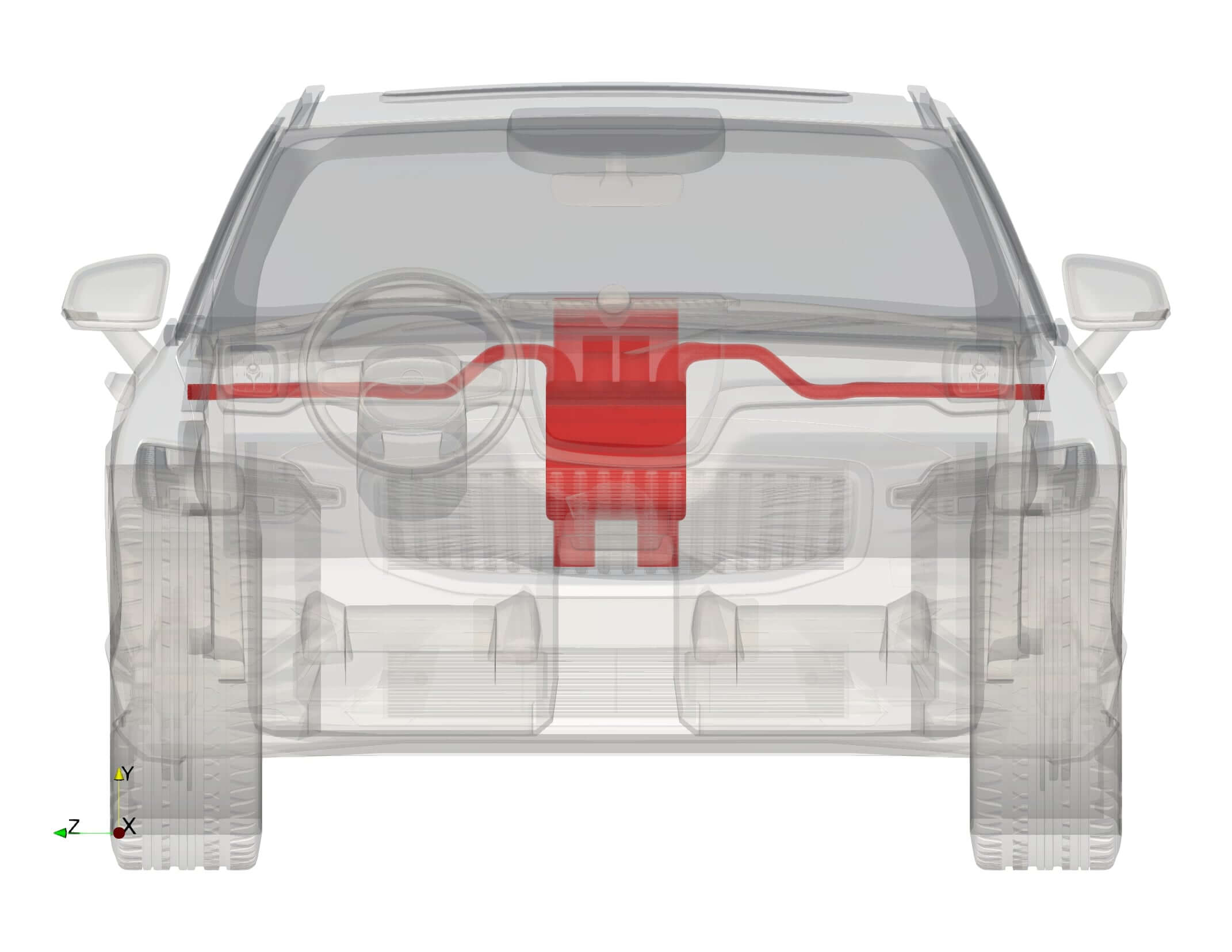
CAE has advanced in conjugate heat transfer simulation. The model analyzes a vehicle's chassis to determine how heat affects solid and plastic components. High-quality meshes are crucial for intricate geometries. Thin-layer meshing creates high-resolution elements in thin solids, allowing engineers to capture thermal gradients, heat transfer, and fluid dynamics while maintaining computational efficiency.
Mesh refinement and element sizing guidelines: Increase mesh density at solid-fluid interfaces to accurately resolve temperature jumps and heat flux
Boundary layer resolution: Use inflation layers for accurate velocity and temperature gradients near walls in convection-dominated cases (see the figure)
Thin solids meshing: Structured hexahedral or prism elements are used in thin regions to maintain accuracy without excessive element count
Gradual transitions: Avoid abrupt changes in element size to prevent numerical instabilities and ensure smooth convergence of the solution
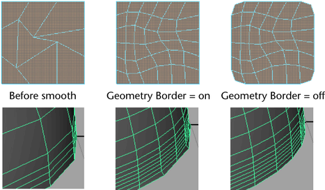
Adaptive refinement: Use solver-based adaptive meshing to dynamically refine areas with high thermal gradients.
Boundary conditions
Defining boundary conditions, such as wall temperature, is vital for reliable simulation. Accurate conditions reflect the physical situation, ensuring the integrity of the temperature field. Solid and fluid domains require careful treatment of the interface in conjugate heat transfer. Conditions in solids specify the temperatures or heat fluxes at surfaces that interact with a fluid.
CFD tools can treat flow and solid domains as interconnected, exchanging wall temperatures at interfaces governed by different physical laws. Convective conditions describe heat exchange with a fluid and incorporate the convective heat transfer coefficient and the ambient temperature. In fluid domains, conditions include inflow and outflow velocities, wall temperature, and pressure.
Solver settings
Choosing the right solver and convergence criteria can guarantee accurate conjugate heat transfer simulations. The choice between segregated and coupled solvers hinges on the intensity of the solid-fluid interaction. Coupled solvers ensure stability in strong interactions, while segregated solvers lower costs in weaker coupling. Regarding flow regimes, pressure-based solvers are suited to low-speed flows, while density-based solvers are well-suited to high-speed compressible flows; selecting appropriate turbulence models is also important for simulation accuracy and convergence.
Initial conditions should be set close to expected solutions. A temperature field initialized near the anticipated result shortens the transient the solver must traverse and reduces the risk of divergence in strongly coupled cases. Patching the solid at an estimated operating temperature rather than at ambient temperature is common practice.
If radiation is significant, especially at high temperatures, include DO (Discrete Ordinates) or S2S (Surface-to-Surface) models.
Turbulence modeling
Turbulence modeling cannot be ignored in heat transfer because it influences fluid behavior and mixing. This results in heat transfer coefficients 2 to 10 times higher than those in laminar flow. Heat transfer is primarily governed by conduction in laminar flow, with a Nusselt number (Nu) of 3.66 for fully developed laminar flow in a circular pipe at constant wall temperature and 4.36 at constant wall heat flux. In contrast, turbulent flow can achieve Nu > 100. This means stronger convective heat transfer due to increased mixing and energy transport.
The k-ω SST turbulence model ensures reliable boundary-layer resolution, effectively capturing near-wall flow characteristics and providing accurate predictions in turbulent regimes.
Hybrid RANS/LES models can be highly effective at capturing transient effects, such as unsteady flow patterns and vortex dynamics, thereby improving predictions of heat transfer rates and overall system behavior in complex thermal environments.
Reaching convergence
Convergence criteria require precise definition. Momentum, energy, and turbulence residuals should be below 10⁻⁴ to 10⁻⁶, with energy ideally at 10⁻⁶ for reliable predictions.
Verifying heat flux balance at solid-fluid interfaces confirms thermal equilibrium. Monitoring temperature and velocity profiles ensures consistency, while adjusting iterative under-relaxation factors can enhance stability in complex cases. Proper tuning leads to realistic CHT simulations.
Transient heat transfer
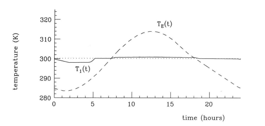
Transient phenomena in solids and fluids exhibit varying time scales. Solids typically exhibit slower thermal responses because the response time of a solid layer scales with L²/α, where L measures its thickness and α its thermal diffusivity. A thick layer, therefore, responds over hours, even when its thermal diffusivity is higher than that of the adjacent fluid, while the fluid itself adjusts within seconds, because flow continuously replaces the fluid in contact with the surface. In the summertime, a house with massive stone walls remains cool due to the stone's high thermal inertia. During the day, the solid walls absorb heat from the sun, and the interior remains cooler than the outside air.
The walls gradually release stored heat at night, maintaining a comfortable interior temperature. In fluid heat transfer, transient conduction describes the temporal evolution of temperature through a fluid medium due to temperature differences.
Transient conduction equations
The transient conduction equation is a partial differential equation that describes this phenomenon:
∇·(κ∇T) = ρc (∂T/∂t)
where ρ, c, and κ are the usual material properties (density, specific heat capacity, and thermal conductivity) of the fluid. Adding a heat sink or heat source term "q," it becomes:
∇·(κ∇T) + q = ρc (∂T/∂t)
The unsteady-state heat conduction equation for the solid is, in a similar fashion, with the possibility of a heat sink or heat source term "q":
∇·(κₛ∇T) + q = ρₛcₛ (∂T/∂t)
Now, transient phenomena in heat transfer manifest distinct time scales in solids and fluids, with their thermal responses governed by thermal diffusivity and material properties. This phenomenon is illustrated by the cooling behavior of a house with massive stone walls during summertime, shedding light on the interplay among heat-transfer mechanisms.
The governing time scale is L²/α, so thickness contributes as much to the transient response as thermal diffusivity.
Solid-flow interface
The temperature field and heat flux are continuous at the solid-flow interface, where a unique interface temperature is determined by the adjacent solid and fluid temperature fields. Nevertheless, in a moving fluid, the temperature field can exhibit rapid fluctuations: near the solid, the fluid's temperature closely mirrors that of the solid, whereas farther from the interface, it aligns with the inflowing or ambient fluid temperature.
Key dimensionless numbers, such as the Reynolds, Prandtl, and Nusselt numbers, characterize CHT behavior. The Reynolds number determines the flow regime and, therefore, the mixing available for convective transport. The Prandtl number fixes the relative thickness of the momentum and thermal boundary layers. The Nusselt number expresses the ratio of convective to conductive transport at the wall and converts a computed wall heat flux into a heat transfer coefficient.
The thermal boundary layer is the region where the fluid temperature transitions from the solid-equivalent temperature to the bulk-fluid temperature. The thermal boundary layer dimensions, which are about the dimensions of the momentum boundary layer, are expressed with the Prandtl number.
The Prandtl number reflects the ratio of momentum diffusivity to thermal diffusivity. Achieving a Prandtl number of 1 necessitates equivalence between thermal and momentum boundary layer widths. A thicker momentum layer would yield a Prandtl number surpassing 1. Conversely, a Prandtl number below 1 signifies a thinner momentum boundary layer than the thermal boundary layer. For laminar flow over a flat plate, the ratio of the two thicknesses approximates Pr¹ᐟ³.
As a reference, the Prandtl number for air at atmospheric pressure and 20 °C is 0.71.
For water at 20 °C, the Prandtl number is about 7.0.
Reference: Nuclear Power, "Prandtl Number of Water and Air," accessed August 20, 2026
These values reflect the relative importance of momentum diffusivity (kinematic viscosity) to thermal diffusivity in each fluid.
| Number | Definition | What it decides in a CHT problem | Reference values in the text |
|---|---|---|---|
| Reynolds, Re | Ratio of inertial to viscous forces | The flow regime, and therefore the mixing available for convective transport | Turbulent flow raises h by a factor of 2 to 10 over laminar |
| Prandtl, Pr | Ratio of momentum diffusivity to thermal diffusivity | The relative thickness of the momentum and thermal boundary layers; for laminar flow over a flat plate the ratio approximates Pr¹ᐟ³ | Air at 20 °C: 0.71. Water at 20 °C: about 7.0 |
| Nusselt, Nu | Ratio of convective to conductive transport at the wall | Converts a computed wall heat flux into a heat transfer coefficient | 3.66 for fully developed laminar pipe flow at constant wall temperature, 4.36 at constant wall heat flux, above 100 in turbulent flow |
| Biot, Bi | hL/κ, comparing internal conduction resistance with surface convection resistance | Whether the solid can be treated as isothermal, or whether the conduction field must be resolved | Below about 0.1, lumped capacitance is sufficient; near or above 1, internal gradients govern |
Mathematics of conjugate heat transfer: looking for analytical solutions
The heat diffusion equation describes how temperature evolves within a medium. Solving it analytically can be complex, but solutions exist for simple cases with well-defined boundary conditions. Let us consider a rod of length L, initially at a uniform temperature T₀, with one end fixed at a constant temperature (Dirichlet condition) and the other insulated (Neumann condition). We use variable separation to determine the temperature distribution over time by decomposing the solution into spatial and temporal components.
The resulting solution expresses temperature as a sum of modes, each decaying over time due to heat conduction. These modes describe heat energy phenomena along the rod, with faster-decaying modes smoothing out temperature variations more quickly.
The key takeaways are:
Heat spreads over time, with sharp temperature differences fading away
The solution consists of multiple “modes,” each contributing to the overall temperature profile
Higher modes decay faster, meaning the rod gradually approaches thermal equilibrium
This approach helps predict how heat evolves in practical applications such as thermal insulation, metal cooling, and heat exchangers.

Numerical methods: solving complex equations
Conjugate heat transfer simulations use numerical methods to model heat conduction and convection. Finite Element Analysis (FEA), the numerical method underpinning structural analysis, addresses heat transfer in solids, while Computational Fluid Dynamics (CFD) models fluid and air energy transport, including phase changes. Accurately representing temperature fields in solids yields more accurate thermal boundary-layer temperatures in fluids.
Choosing appropriate numerical techniques and solvers ensures accuracy. Thoughtful selections of discretization schemes and algorithms clarify energy transport in conjugate systems.
More insight into FEA, CFD, and temperature distribution prediction
FEA and Computational Fluid Dynamics (CFD) are powerful numerical techniques for modeling complex thermal phenomena. These methodologies are widely used in engineering and scientific disciplines to analyze temperature distribution, fluid flow, and heat transfer in complex systems.
FEA involves partitioning a given domain into discrete elements, enabling precise approximations of temperature profiles. This procedure, known as discretization, allows the representation of intricate geometries and material properties. The complete temperature profile for each element can be expressed using interpolation functions, and the system's behavior is characterized by a set of algebraic equations.
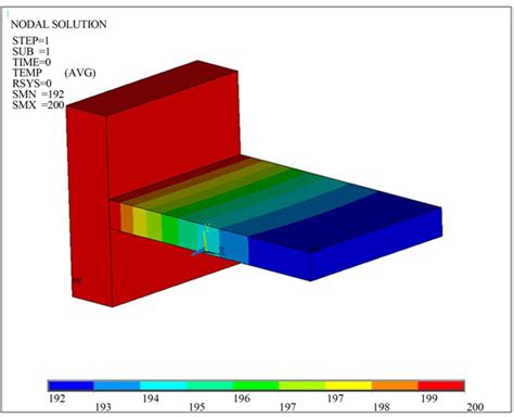
Temperature distribution with FEA (10.4236/aast.2018.33004)
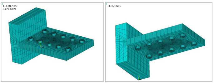
CFD uses mesh divisions to model turbulent flows and energy transport. The Navier-Stokes and energy equations govern turbulent fluid flow, with additional models closing the turbulence physics by approximation, and they account for heat exchange and the coupling between motion and thermal effects.
Incorporating the energy equation provides a comprehensive representation of fluid behavior and energy transport, thus:
rate of change + convective transport = conductive transport + sources
i.e.:
ρc (∂T/∂t + u⋅∇T) = ∇⋅(κ∇T) + q
AI and CAE simulation
Deep learning, a branch of machine learning, detects patterns in large datasets and predicts outcomes from them. Trained on simulation results or experimental datasets such as wind tunnel campaigns, as in AI-powered CFD tools for urban wind and climate analysis, a model returns field predictions in a fraction of the time a solver requires. Combined with CAE simulation, it allows engineers to explore a far larger number of candidate designs.
Convolutional Neural Networks (CNNs), developed for computer vision, identify patterns in images, and their geometric counterparts extract features directly from 3D representations, enabling predictions to follow shape changes in complex CAD geometries. Neural Concept applies these models as its physics-aware AI platform, the intelligence layer above the existing engineering stack.
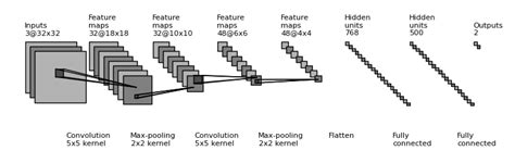
Typical structure of a CNN from input (left) to output (right)
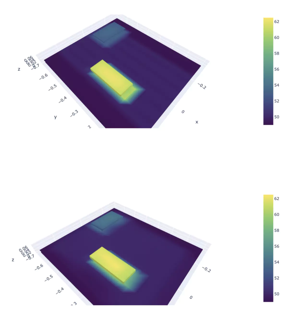
Neural Concept trains models on CAD geometry and simulation results to return thermal field predictions in near real time. This enables engineers to quickly identify design flaws and optimization opportunities that traditional CFD and CHT methods might miss due to computational constraints. In January 2026, the company extended the platform with an AI Design Copilot combining spatial reasoning, physics awareness, and CAD-ready geometry generation.
Reference: Neural Concept, "Neural Concept Introduces a Physics- and Geometry-Aware AI Design Copilot, Extending Its Established Engineering AI Platform," January 7, 2026
Engineering applications of conjugate heat transfer
Conjugate heat transfer has widespread applications in engineering fields such as electronics cooling, engine thermal management, and aerospace design.
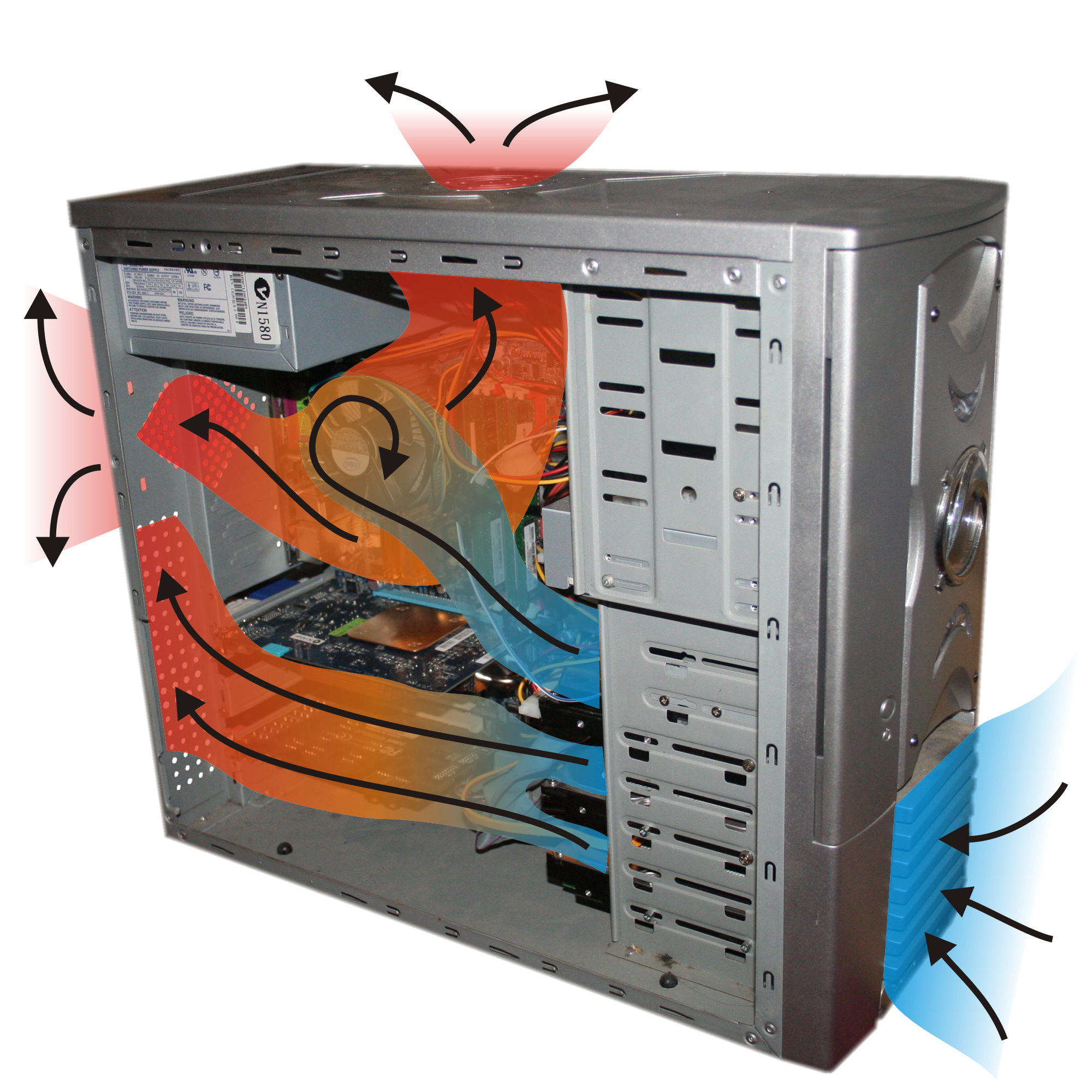
Conjugate heat transfer, coupled with modern simulation tools, is an indispensable analytical tool in engineering domains rooted in technical precision, from electronics cooling to aerospace engineering and industrial processes. In the automotive industry, CAE tools used throughout vehicle development increasingly rely on CHT to predict underhood temperatures, brake cooling, and battery pack thermal behavior. For instance, conjugate heat transfer allows engineers to optimize cooling solutions and extend the lifespan of electronic components.
The sections below provide additional information, and the Neural Concept website focuses on other data-driven workflow applications.
Cooling systems applications
CHT analysis is critical for thermal management in power electronics and IC packages, particularly for hotspot mitigation in high-power-density applications such as GaN transistors and multi-core processors. Engineers use these simulations to optimize thermal interface materials (TIMs) and evaluate junction-to-ambient thermal resistance in various cooling solutions. Engineers use conjugate heat transfer simulations to analyze geometries, such as heat sinks and microchannels, coupled with fluid flow dynamics.
Heat exchanger applications and conjugate heat transfer
The field of heat exchangers, integral to diverse industrial processes, benefits from conjugate heat transfer analysis. The effective thermal energy exchange between fluid streams is essential in applications from HVAC system design to chemical processing.
With CHT simulation, engineers evaluate heat transfer coefficients, pressure drops, and thermal gradients, enabling precise parameter tuning for optimal performance.
This comprehensive analysis culminates in better energy usage and reduced operational expenditures.
Typical examples of heat exchangers and their simulations are:
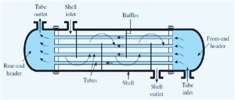
1. Shell-and-tube heat exchangers are used in oil refining and chemical processing. CHT analysis optimizes flow arrangements and tube layouts, enhancing heat transfer while minimizing pressure losses.
2. Plate heat exchangers are standard in food and beverage processing. They benefit from CHT simulations that optimize plate design and spacing. The analysis identifies optimal flow paths to maximize heat transfer and minimize fouling, which is crucial for product quality and reduced cleaning costs.
3. Air-cooled heat exchangers: These are used in power plants and HVAC systems. They use ambient air for heat dissipation. CHT analysis optimizes fin design and airflow patterns, enhancing cooling performance while accounting for environmental factors such as wind and temperature fields.
4. Double-pipe heat exchangers often heat or cool one fluid through another. CHT simulations enable precise modeling of heat transfer and fluid dynamics. Analyzing fluid interaction allows engineers to optimize the design for maximum thermal performance, reducing energy consumption.
Automotive applications: braking system conjugate heat transfer simulation
The first of two applications concerning car design and car manufacturing is brakes.
During aggressive braking events, the friction couple (rotor-pad interface) experiences thermal loading that raises rotor surface temperatures from about 300 °C under mild braking to 700 °C or more in severe or repeated events. For cast iron rotors paired with organic or semi-metallic pads, the friction coefficient can drop to 0.2 above roughly 350 °C, leading to thermal fade and potential pad glazing. CHT analysis helps optimize brake caliper designs and rotor ventilation geometry to maintain optimal brake torque coefficient while preventing thermal shock-induced disc coning.
Reference: Archives of Automotive Engineering, "Brake disc temperature prediction in fade test using Computational Fluid Dynamics aero-thermal simulation," accessed August 20, 2026
Ventilation and cooling: Evaluation of the effectiveness of cooling mechanisms, such as ventilation channels or ducts, to mitigate temperature rise in critical brake components
Materials: Suitable materials with optimal thermal properties for enhanced heat dissipation and durability
Performance enhancement: Improved braking performance, reduced wear, and extended component lifespan
Underhood conjugate heat transfer simulation
CHT simulations provide vital insights for developing vehicle thermal management.
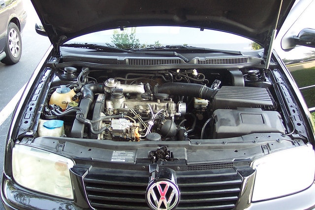
Internal combustion engines generate heat, which is reflected in the vehicle's underhood area, which houses heat sources such as the engine and exhaust system. Engineers use conjugate heat transfer (CHT) simulation to optimize cooling performance and ensure adequate heat dissipation from critical components.
CHT simulation models heat transfer in the engine bay, evaluating how heat is conducted through components and convected by air or coolant.
Analysis can identify potential overheating issues and assess the cooling system's effectiveness by simulating engine load and airflow patterns.
Moreover, CHT simulations help design components such as radiators and fans to maximize heat exchange.
Examples of conjugate heat transfer in industrial processes
Conjugate heat transfer analysis is crucial for industrial processes, impacting manufacturing and energy conversion. This analysis models solid components and fluid flows in equipment, providing insights into heat transfer rates, temperature distributions, and thermal stresses. Engineers use these insights to optimize designs and operational parameters, thereby lowering energy consumption and informing AI applications in civil engineering infrastructure where large heat-exchange systems and thermal stresses must be accounted for in long-term performance.
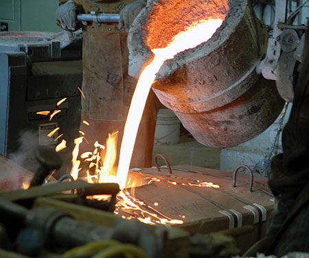
Engineers employ conjugate heat transfer analysis in metallurgy to optimize cooling strategies for processes such as continuous casting. This method simulates the heat exchange between metal and cooling water. Likewise, engineers use this method in the chemical processing sector to manage reaction kinetics and temperature variations, thereby improving yield, selectivity, and safety.
Conjugate heat transfer analysis (CHT) is fundamental in thermal modeling in power generation. In gas turbines, first-stage nozzle guide vanes and rotor blades are exposed to gas-path temperatures that exceed 1300 °C, while the nickel-based superalloys from which they are cast reach their creep limit above about 1000 °C. Thermal barrier coatings recover 100 to 300 °C of that margin, and internal cooling supplies the remainder. CHT analysis optimizes internal cooling channel geometries, including serpentine passages and pin-fin arrays, to maintain acceptable metal temperatures while minimizing parasitic pressure losses. Engineers use these simulations to evaluate film cooling effectiveness η and overall cooling effectiveness φ.
Reference: npj Materials Degradation, "Calcia magnesia alumino silicate (CMAS) corrosion attack on thermally sprayed thermal barrier coatings: a comprehensive review," April 25, 2024
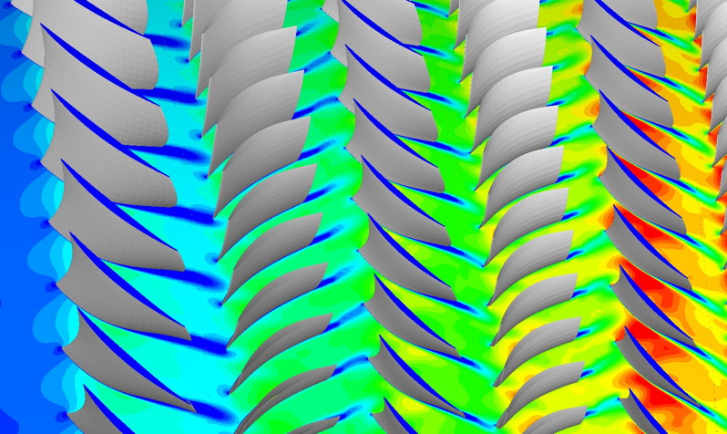
This approach minimizes thermal stresses and boosts the turbine's performance and lifespan.
Conclusions on CHT
In this article, we have progressed from physics to mathematics to numerical solutions and, finally, the CHT engineering applications.
CHT analysis gives engineers reliability in thermal simulations and a defensible basis for optimizing designs. This multidisciplinary approach combines CFD simulations with thermal analysis of solids. It enables engineers to understand the interaction between fluid flows and solid components, improving brake systems' performance and underhood thermal management in automotive engineering.
CHT analysis will remain crucial in fields such as industrial processes and aerospace exploration. Trained on solver results, physics-aware AI extends its reach by returning predictions early enough to influence design decisions.
When the coupled field has to be known early
A conjugate calculation gives the right answer and gives it late. The mesh has to resolve the boundary layer on one side and the thin solid on the other, the coupling has to converge, and the result describes one geometry. A model trained on a company's own archive of conjugate runs reads the geometry and returns the coupled temperature field directly, so a fin pitch, a channel layout or a duct routing can be judged while it is still a choice. Neural Concept delivers this as an Intelligence Layer for Engineering for physical products, above the CAD and CAE tools already in use, with an AI Design Copilot that answers inside the design loop.
The gain shows up where the thermal path sets the design. Eaton applied it to cooling plates and gained more than 30% in pressure drop and more than 10% in weight. MAHLE explored 30 million design iterations on a radial blower for automotive HVAC, reaching 15% higher efficiency with 4 dB less noise. Neither replaces the solver, which remains the reference; both change how many geometries reach evaluation before one is committed.
Ready to see the coupled temperature field while the geometry is still open?
Explore the platform →FAQ
What is the difference between conduction, convection, and radiation?
Conduction is the primary mode of heat transfer through solids. Convection is heat transfer via fluid movement, free or forced. Radiation is the transfer of energy through electromagnetic waves.
Why is conjugate heat transfer important in engineering simulation?
CHT models interactions between solid and fluid domains, ensuring accurate thermal predictions for heat exchangers, turbines, and electronics cooling.
What are the best practices for setting up a conjugate heat transfer simulation?
Refine mesh near solid-fluid interfaces. Use appropriate turbulence models. Apply accurate boundary conditions and monitor residuals and energy balance.
Which software tools simulate conjugate heat transfer?
ANSYS Fluent, COMSOL Multiphysics, OpenFOAM, and Simcenter STAR-CCM+ are used to simulate CHT in engineering applications. They can all feed the Neural Concept platform for data-driven predictions.
How does the convective heat transfer coefficient affect thermal performance?
Higher coefficients enhance heat dissipation, while lower values improve thermal insulation. The optimal value depends on the application.
What is the Biot number, and how does it determine whether a full CHT analysis is needed?
The Biot number equals hL/κ, where h is the convective heat transfer coefficient, L is the characteristic length of the solid (volume divided by wetted surface area), and κ is the thermal conductivity of the solid. It compares internal conduction resistance with surface convection resistance. Below about 0.1, the solid remains nearly isothermal, and a lumped-capacitance model with a prescribed convective boundary condition is sufficient. Near or above 1, internal gradients govern the result, and the conduction field must be resolved. A full CHT treatment becomes necessary when the wall temperature also feeds back on the flow, since the coefficient h is then unknown in advance.
What is the Robin boundary condition, and how does it couple solid and fluid domains in CHT?
The Robin condition, also called the third-kind or mixed condition, prescribes a linear combination of temperature and its normal derivative at a surface: −κ ∂T/∂n = h(T꜀ − T∞). It represents convection to an environment at temperature T∞ without resolving that environment. A conjugate calculation replaces the assumed h with two interface conditions, temperature continuity and heat flux continuity, applied at the interface between the two meshes. Partitioned solvers, which advance the solid and the fluid separately, exchange Robin-type data at each coupling step because passing a temperature to one side and a flux to the other tends to destabilize the iteration when the conductivity ratio is large.
How is conjugate heat transfer modeled in lithium-ion battery packs during fast charging?
Heat generation inside each cell combines an irreversible ohmic term proportional to the square of the current and a reversible entropic term proportional to the temperature derivative of the open-circuit voltage. That volumetric source enters the conduction equation for the jelly roll, whose conductivity is strongly anisotropic, with in-plane values an order of magnitude above through-plane values. The conduction field is then coupled to the coolant flow in cold plates, serpentine channels, or immersion loops. Design targets are a cell temperature held between roughly 15 °C and 35 °C and a cell-to-cell difference below about 5 °C, since gradients above that level accelerate uneven aging across the module.
Reference: Journal of Energy Storage, "Lithium-ion battery thermal modeling and characterization: A comprehensive review," 2025
How does contact resistance at solid-solid interfaces affect a CHT model?
Two solids in nominal contact touch only across a small fraction of the apparent area, and the gaps are filled by air or by an interstitial material. The resulting thermal contact resistance produces a temperature jump across the joint equal to the heat flux multiplied by that resistance. Ignoring it results in the predicted junction temperature being below the measured value, sometimes by tens of degrees in electronic packages. In a CHT model, the joint is represented as a thermal resistance or an equivalent conductance on the coupled interface, with the value taken from measurement or from a correlation based on surface roughness, contact pressure, and the microhardness of the softer material.
Reference: Electronics Cooling, "Calculating interface resistance," May 1, 1997
How are moving meshes handled in CHT simulations for rotating machinery such as pumps or turbines?
Two treatments are standard. The multiple reference frame approach, also called the frozen rotor, solves the rotating zone in a rotating frame while keeping the mesh fixed, which is suitable for steady analyses in which the relative position of the rotor and stator does not dominate the results. The sliding mesh approach physically rotates the mesh and passes fluxes across a non-conformal interface, thereby resolving blade passing and the unsteady wake. The solid domain rotates with its zone, so conduction is solved in the rotating frame, and the centrifugal contribution to the flow appears as a source term. The disparity between fluid and solid time scales is handled by loose coupling: the fluid advances on its own time step, and the solid temperature is updated at longer intervals or solved to steady state using time-averaged wall fluxes.
Sources
The foundational and standard references behind the physics above, which are not linked in the text:
J. B. J. Fourier, Théorie analytique de la chaleur, 1822 — the conduction law and the heat diffusion equation used throughout.
J.-B. Biot, early nineteenth-century experiments on heat flow through materials, the origin of the Biot number.
F. R. Menter, Two-equation eddy-viscosity turbulence models for engineering applications, AIAA Journal, 1994 — the k-ω SST model recommended above.
Newton's law of cooling, Q = hA ΔT, and the Nusselt, Prandtl and Reynolds groups, as set out in the standard heat transfer texts (Incropera and DeWitt, Fundamentals of Heat and Mass Transfer; Bejan, Convection Heat Transfer).
The solvers named in the FAQ: ANSYS Fluent, COMSOL Multiphysics, OpenFOAM and Simcenter STAR-CCM+.
The data and case sources are linked inline in the sections above: Engineering ToolBox for conductivity and convective coefficients, Engineers Edge for thermal diffusivity, Nuclear Power for Prandtl values, Archives of Automotive Engineering for brake disc temperatures, npj Materials Degradation for thermal barrier coatings, the Journal of Energy Storage for battery thermal modelling, and Electronics Cooling for contact resistance.
Appendix — notation
CHT — conjugate heat transfer: conduction in the solid and convection in the fluid solved together
T, ΔT — temperature and temperature difference; ∇T — the temperature gradient
κ — thermal conductivity, in W/(m·K); ρ — density; c — specific heat capacity
α — thermal diffusivity, κ/(ρc), in m²/s; the transient response of a layer scales with L²/α
h — convective heat transfer coefficient, in W/(m²·K); an input in classical analysis, an output in CHT
q — volumetric heat source or sink
Re, Pr, Nu, Bi — Reynolds, Prandtl, Nusselt and Biot numbers, as tabulated above
FVM, FEM, FDM — finite volume, finite element and finite difference methods
FEA — finite element analysis; CFD — computational fluid dynamics
RANS, LES — Reynolds-Averaged Navier-Stokes and Large Eddy Simulation; k-ω SST — the shear stress transport two-equation model
DO, S2S — discrete ordinates and surface-to-surface radiation models
TIM — thermal interface material
Dirichlet, Neumann, Robin — boundary conditions prescribing temperature, flux, and a combination of the two